19DORMA
L1
N
35 mm
6 mm
6 mm
150 mm
L1
N
6x
4.
2.
3.
1.
1.
3.
2.
5.
4.
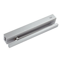
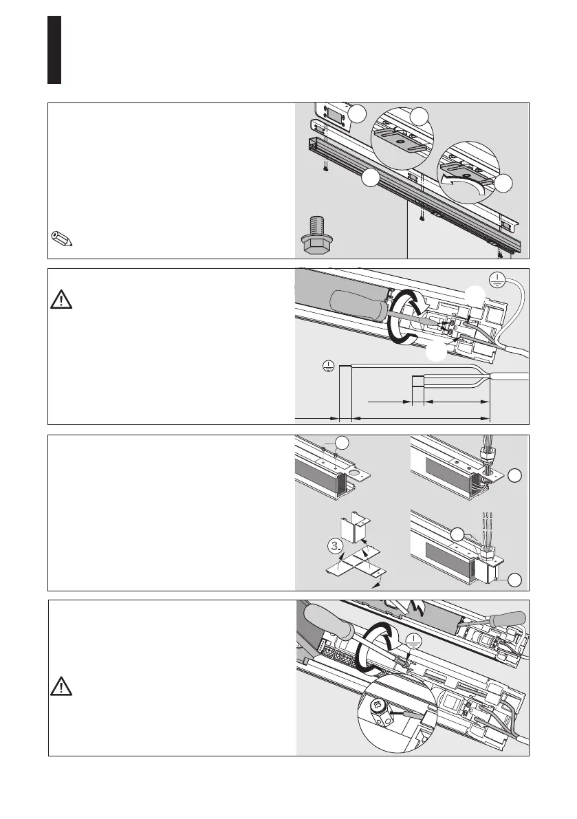
1. Adhere 3 pieces of felt equally onto the
bracket.
2. The openings of the door panel
suspension have to point to the front
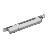
3. Wenn using MANET fixings, the door
panel suspensions have to be
unscrewed.
4.
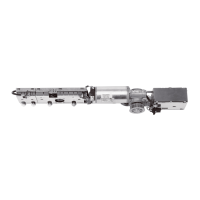
Fix the operator below the bracket with
6 hexagon screws (lock screws) (8 Nm).
You will have to move the carrier in order to
reach all 6 holes.
Connection of 120 V permanent power supply.
Working on electrical equipment may only
be performed by properly qualified staff
(electricians). Before starting with the
installation, make sure that the power
supply lines are dead (disconnected).
Loosentheendstopandmoveittothecenterof
the system (see page 13, picture in the middle).
Cut the leads to length, dismantle them and
connectL1andNtotheconnectionterminalsof
the power supply.
When connecting to conduit, use the included
conduit cover, mounting plate and phillips
screws
Step:
1. Attach plate to operator with (2) screws.
2.
Route the wires and connect to the
operator.
3.
Fold the conduit cover as shown.
4. Hook conduit cover to the plate.
5.
Secure conduit cover onto the plate with
remaining screw.
Leveroutthecoveratthecontrolunithousing
with the aid of a screwdriver.
Laythegroundinglinethroughthehousingof
the operator as shown in the picture and connect
it to the grounding terminal (PE).
The grounding (PE) has to be connected in
any case.
Connect all external accessories but the safety
sensors. Please refer to the instructions for the
cable channel on page 30.
Installation and Maintenance Manual
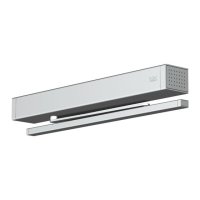
CS 80 MAGNEO
—
 Loading...