26 DORMA
1.
3.
2.
5.
4.
L1
N
35 mm
6 mm
6 mm
150 mm
L1
N
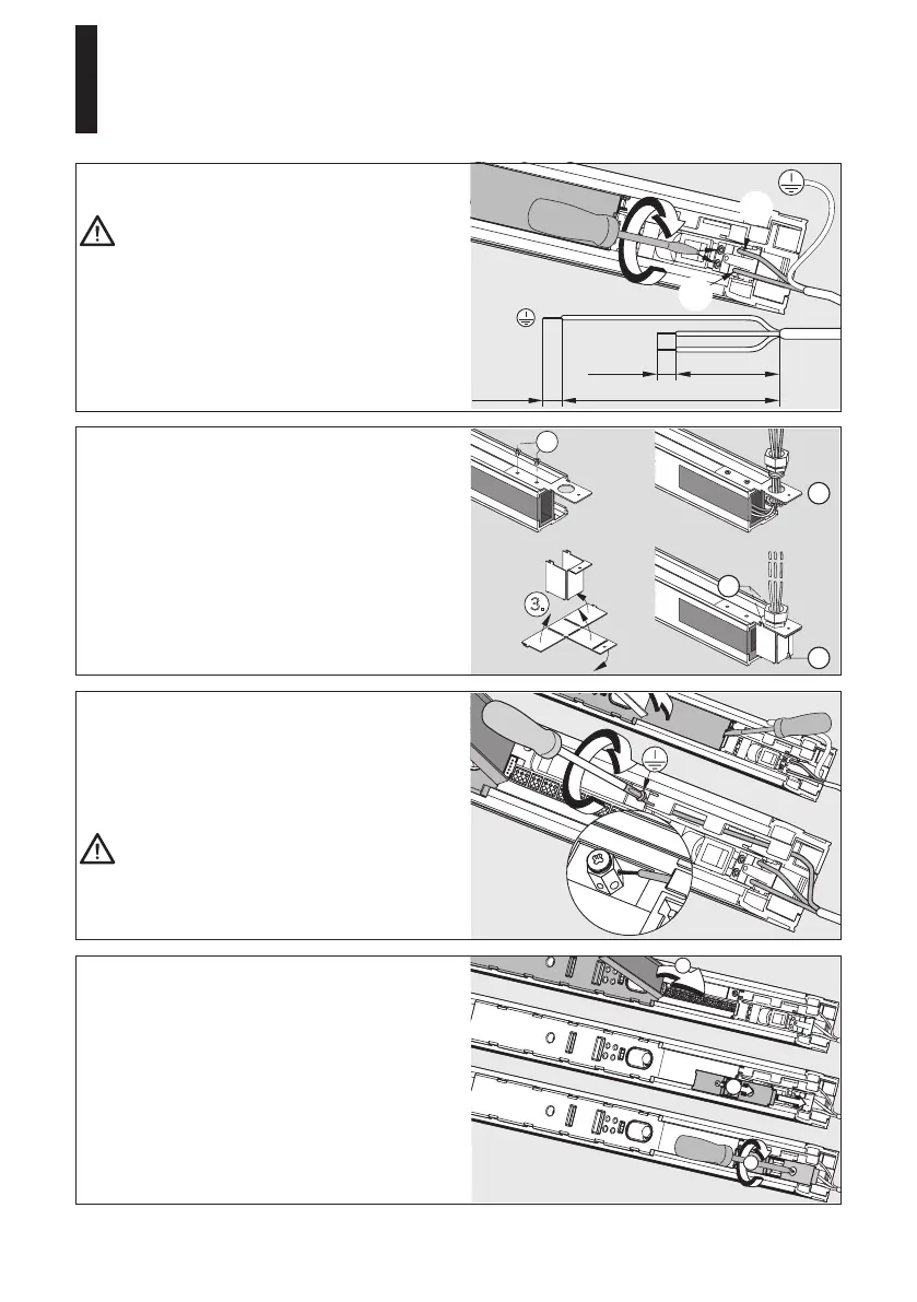
Connection of 120 V permanent power supply.
Work on ellectrical equipment may only be
performed by properly qualified staff
(electricians) before starting with the
installation, make sure that the power supply
lines are dead (disconnected).
Relax the end stop and move it to the center of
the system (see page 13, picture in the middle).
Cut the leads to length, dismantle them and
connectL1andNtotheconnectionterminalsof
the power supply.
Lever
outthecoveratthecontrolunithousing
with the aid of a screwdriver.
Laythegroundinglinethroughthehousingof
the operator as shown in the picture and connect
it to the grounding terminal (PE).
The grounding (PE) has to be connected in
any case.
Connect all external accessories but the safety
sensors. Please refer to the instructions for the
cable channel on page 30.
Close the cover of the control unit housing. Fix
and screw down the cover of the power supply
housing. Move the end stop to the end of the
channel and screw it down thoroughly
(see page14, picture at the bottom).
When connecting to conduit, use the included
conduit cover, mounting plate and phillips
screws
Step:
1. Attach plate to operator with (2) screws.
2.
Route the wires and connect to the
operator.
3.
Fold the conduit cover as shown.
4. Hook conduit cover to the plate.
5.
Secure conduit cover onto the plate with
remaining screw.
Installation and Maintenance Manual
CS 80 MAGNEO
—
 Loading...