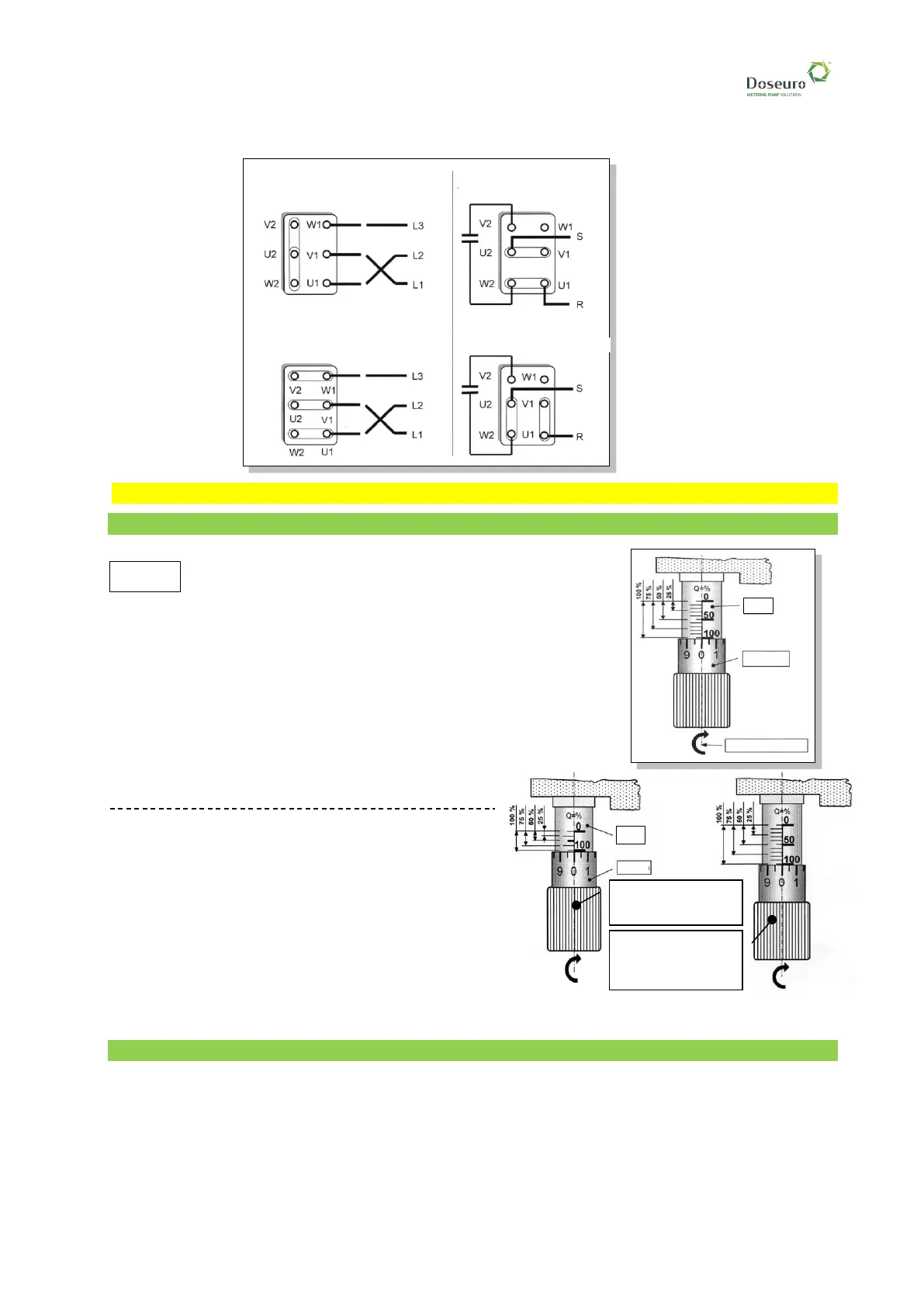
DIAGRAM FOR CONNECTING MOTORS TO ENERGY SOURCES
11 - PUMP ADJUSTMENT
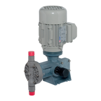
11.1 - Stroke variation with manual system
11.1.1 - Standard stroke variation
The variation of the pump flow rate from 100% to 0% (zero)
is obtained by turning the adjusting knob clockwise; each
turn corresponds to 1/10 of the piston stroke, verifiable on the .
There are 10 subdivisions on the handle, numbered 0 (zero) to 9 (nine),
each one corresponds to 1/100 of the piston stroke.
11.1.2 - Other stroke types
❑ The pump model. D 050N - stroke 5 mm.
Adjustment from 0% to 100% takes place in 5 rotations, that on the
graduated scale corresponds to 20% of capacity.
There are 20 notches on the knob, each corresponding to 1% of the flow
rate, subdivided into 10 that are long from 0 to 9, and
10 that are short.
❑ The pump model D 100N - D 101N - stroke 10
mm.
❑ The pump model D 121N/D 122N - stroke 12.5
mm.
The three pumps are adjusted from 0% to 100% in 10
turns, which on the graduated scale corresponds to
10% of the flow rate.
There are 20 notches present on the handle, each one
corresponds to 0.5% of flow rate, divided into 10 long
ones, from 0 to 9 and 10 short ones
11.2 - Stroke variation with servo control
❑ Servo command
• If the pump is fitted with servocontrol, the above-described adjustment procedure is no longer valid.
➢ It is necessary to consult the instructions provided with the specific application attached to
the equipment supplied.