To check whether the operation was successful, proceed as follows:
11 Close valve "2", recirculation will begin to recycle the oil, pressure gauge "3" will indicate the
calibration pressure (that must be 10-15% higher than the reading with valve "2" open).
12 By opening valve "2", recirculation will return motionless.
Close valve "4", recirculation will begin to recycle, by opening valve "4" recirculation will return
motionless.
N.B. If air bubbles are noticed when the oil oscillates inside the tank, it means:
When calibrating the reset valve spring, operation in POINT 7, the level has been exceeded (repeat
operations from POINT 7 on).
In case of excessive pressure drops in suction;
➢ Check the filter.
➢ The pipe’s diameter must be greater than the pump attachment and the pipe route must be as
short and as linear as possible and have wide radius curves.
➢ The pump must be installed max 1 m over head, under head is the recommended position.
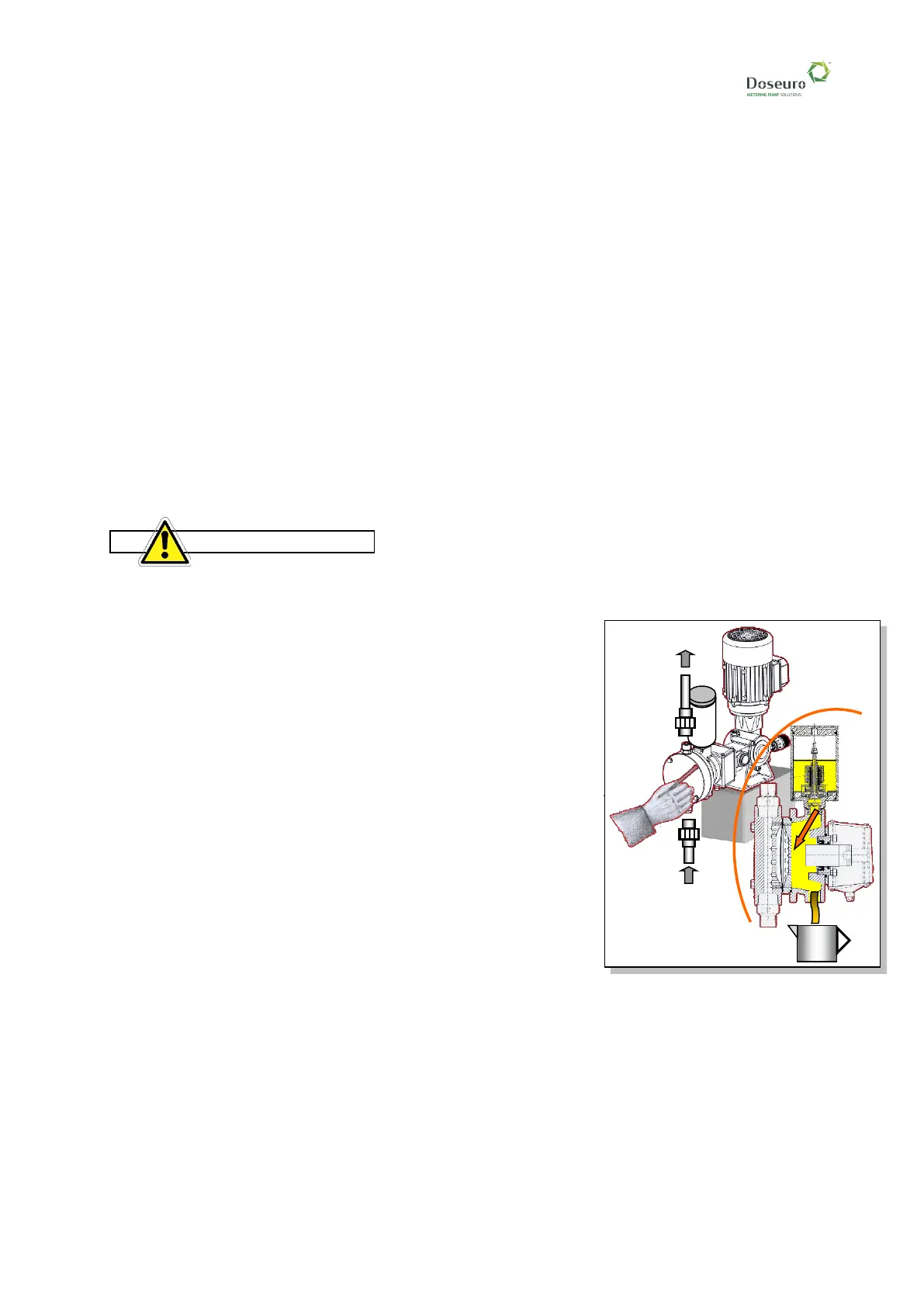
15.4.3 - Pump head disassembly and diaphragm replacement
In this series of pumps, the pump head is directly locked to the oil reservoir; therefore, for any
maintenance intervention to the various components the oil contained in the reservoir must be
drained.
Before operating on the pump, the maintenance personnel must make sure that the pump is
stopped and disconnected from the electrical power supply and that the system is depressurised
and empty.
Proceed as follows:
➢ Disconnect the piping from the valves.
➢ Drain the oil reservoir by unscrewing the plug below it, let the
product drain into a container and dispose of it according to
regulations.
➢ Loosen the screws on the front of the pump head.
➢ Remove the pump head.
➢ Remove the diaphragm; if damaged, replace it.
➢ Remove the oil reservoir.
➢ Remove the gasket support ring from the piston, verify wear
condition of the gasket and the piston, if necessary, replace
them.
Once maintenance operations have been completed, reassemble the components following
the above mentioned operations in reverse order.