7 - CONNECTION OF THE PUMP TO THE SYSTEM PIPES
7.1 - Block removal
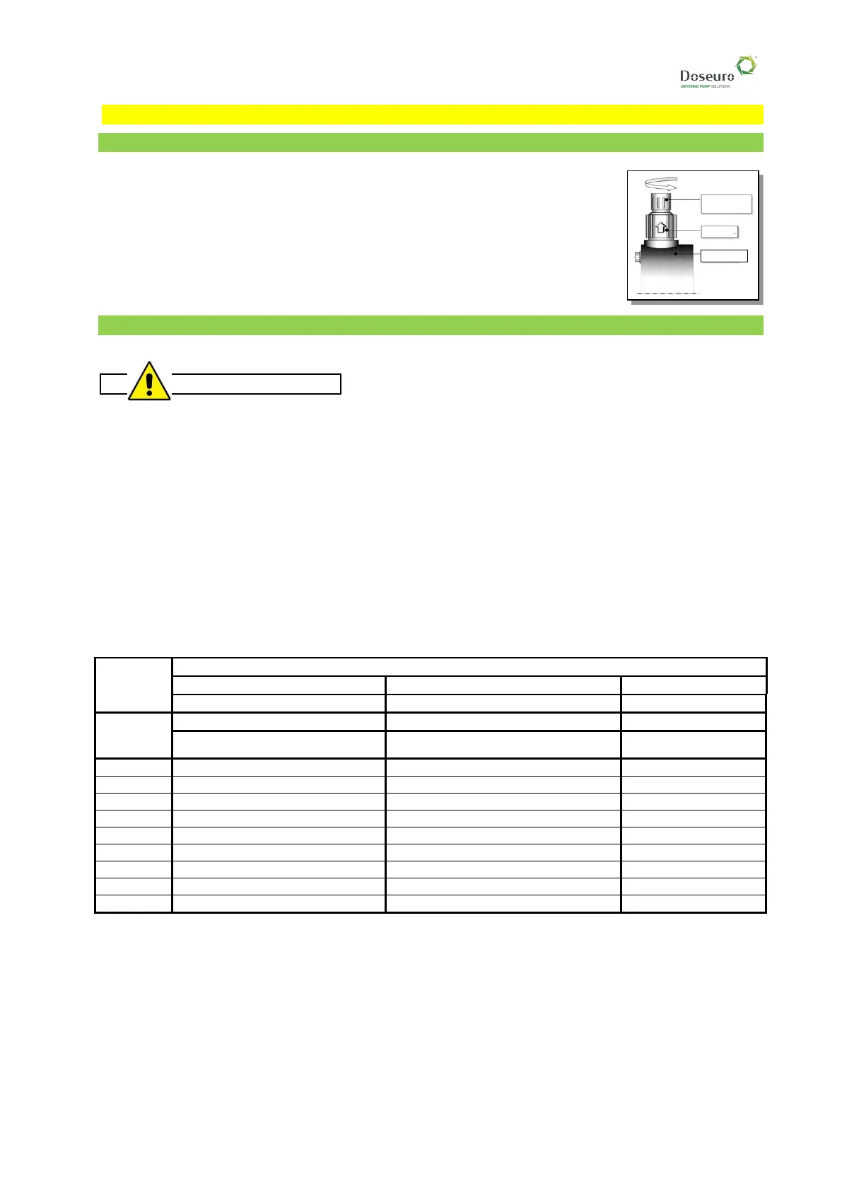
It is necessary to remove the protective caps, located on the suction and delivery
inlets of the valves, before installing the pump
If the pump has been out-of-service for a long period, we recommend checking
that the pump head screws are not loose as well as checking for oil leaks from
the seal gaskets, replacing them if necessary, before installation.
7.2 - Connection to the suction pipe
Suggestions that the installer must follow for a correct installation are listed.
• Before connecting the piping to the pump attachments, clean the pipe to eliminate any foreign bodies,
welding beads, gasket scraps, etc.
• The length of suction pipe must be reduced to a minimum and very linear, using wide radius curves.
• Avoid counterslopes to favour the evacuation of any air bubbles and to ensure that the pipe is
perfectly sealed, especially in order to avoid the disengagement of the pump.
• The suction pipes and fittings must be sized to a nominal diameter at least equal to that of the pump
valves or greater if in the presence of viscous liquids.
• The maximum speed of the fluid in the piping must not exceed 0.7 m/s for liquids with a viscosity of
up to 100 mPa - (cPs).
• The piping must be properly supported so that the weight does not fall on the pump or create tension
on the pump head.
Table for selecting the inner diameters of the piping according to product viscosity and number of pump
strokes.


 To Next Page