14 Dover Fueling Solutions W2940305 Rev 07 8/2019
2.6 Island Construction, Dispenser Anchoring, Piping, and Bollards
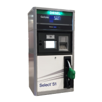
This dispenser is designed to be shelf-mounted. The base of the dispenser contains four
bolt slots that measure 7/16” x 1-7/16” for anchoring the dispenser to the shelf. Allow for
the proper dispenser containment box if required by local, state, or federal regulations.
Reference Appendix A, Dimensions & Base Layouts, for dispenser and shelf dimensions.
Vertical supply risers and electrical conduits must be located per the Installation Drawing
for the appropriate model. Proper height must be maintained to avoid undue stress on the
dispenser. See Section 3.3 for wiring and conduit requirements. Reference Appendix B
for Wiring Diagrams.
Supply piping should be selected and installed based on the product dispensed and in
accordance with local, state, and federal regulations. The piping manufacturer’s
instructions should be followed for the proper trenching, connection, sealing, corrosion
prevention, pressure relief, leak detection, containment, and testing.
DEF dispensers using the internal DEF filter kit require additional clearance under the
base of the dispenser for the DEF filter. See the base layout for details
This dispenser should only be mounted to a UL Listed tank that already has a suitable
means to mount the dispenser to the tank. No modification to the tank is allowed for the
installation of the dispenser.
Bollards must be installed around the dispenser to prevent
vehicles from coming into contact with the dispenser.
Wayne dispensers are specified to work at a maximum normal operating pressure of 50 PSI.
Normal operation can create pressure spikes which may exceed 50 PSI. These normal
spikes are easily handled by the dispenser. Wayne dispensers are designed and tested to
withstand pressures up to 250 PSI, for short durations, without rupture or permanent
distortion. Certain extreme conditions, such as installations with above-ground tanks and
very long runs of pipe, can create pressure spikes that may damage the dispenser and its
accessories. If these conditions exist, measures must be taken to reduce or dampen these
pressure spikes to prevent damage to the equipment.
To maximize flow, position the remote dispenser and tank as close together as possible
and minimize the number of turns in the piping. Consult the submersible pump
manufacturer for the proper sizing of the submersible pump, any necessary leak
detection equipment, and installation details.
Product piping must avoid the creation of vapor in the lines and deliver a minimum
pressure of 25 psi at the remote dispenser inlet when all dispensers connected to the
same submersible pump are operating. The dispenser’s maximum operating pressure is
50 psi.
A listed, rigidly anchored emergency shutoff valve must be installed, in accordance with the
manufacturer’s instructions.
Failure to install the proper emergency shutoff valve will
present a hazardous condition that could result in serious injury and/or environmental
damage.
NOTE: On E85 dispenser models, use shear valve part number 10P-0152E85 manufactured
by OPW.
“Listed” means published on a list by a nationally recognized testing laboratory (NRTL) which is
responsible for product evaluation and is acceptable to the authority having jurisdiction. Underwriters
Laboratories, Inc. is one example of a Nationally Recognized Testing Laboratory. For more information
on NRTL’s, see Title 29, Parts 1907 and 1910 of the Code of Federal Regulations, Safety Testing or
Certification of Certain Workplace Equipment and Materials.
WARNING
WARNING
WARNING

 Loading...