Technical manual | X-am® 3500/8000 13
Description
3 Description
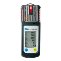
3.1 Product overview
The graphics are displayed on the fold-out page.
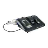
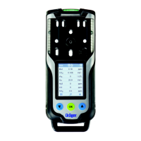
Graphic A
1 Display 4 Charge LED green/red
2 Locking screw for an additional
charging module
5 Labelling field (X-am 8000 only)
3 Power supply unit 6 Induction charger
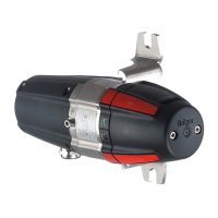
Graphic B
1 Gas inlets 3 Horn
2 Thread port for pumps and calibra-
tion adapter
4 Pump outlet and inlet
Graphic C
1 LED green/yellow/red 2 LED yellow/red
Graphic D
1 feature button 1 3 feature button 3
2 feature button 2
Graphic E
1 Status information 2 Navigation bar
Graphic F
1 Clip (optional) 2 Socket for support belt for shoulder
version
(X-am 8000 only)
Graphic G
1 Alarm A1 3 STEL alarm
2Alarm A2 4TWA alarm
Graphic J
1 Battery pre-alarm 2 Battery main alarm
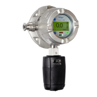
Graphic K
1 Calibration adapter (grey coloured
ring)
3 Exhaust
2 Gas inlet 4 Locking screw
Graphic L
1 Pre-tube bracket (X-am 8000 only) 2 Pre-tube (X-am 8000 only)
Graphic M
1 Pump adapter (blue coloured ring) 4 Exhaust
2 Gas inlet 5 Locking screw
3 Dust and water filter
 Loading...