Horizon Compact Release 1.01.00 Wireless Ethernet Product User Manual – Volume 2
2.2.3 Alignment Adjustment Sensitivity
When aiming the antenna it cannot be over emphasized that you must rotate the adjustment nut(s)
1/10
th
of a turn at a time between taking RSL readings (allow time for the RSL reading to update).
Table 2-3 shows how many degrees the antenna will move when the adjustment nut(s) is rotated
through one full turn.
Table 2-4 shows that the beam width of the typical antenna is often less than the amount of movement
available with one full turn of the aiming adjustment.
Table 2-3 Degrees per Revolution of Adjustment
Antenna Size Change in Elevation (Tilt) Change in Azimuth (Pan)
12” and 24” 2.2 º per full turn of adjustment 1.6 º per full turn of adjustment
36” and 48” 1.3 º per full turn of adjustment 1.1 º per full turn of adjustment
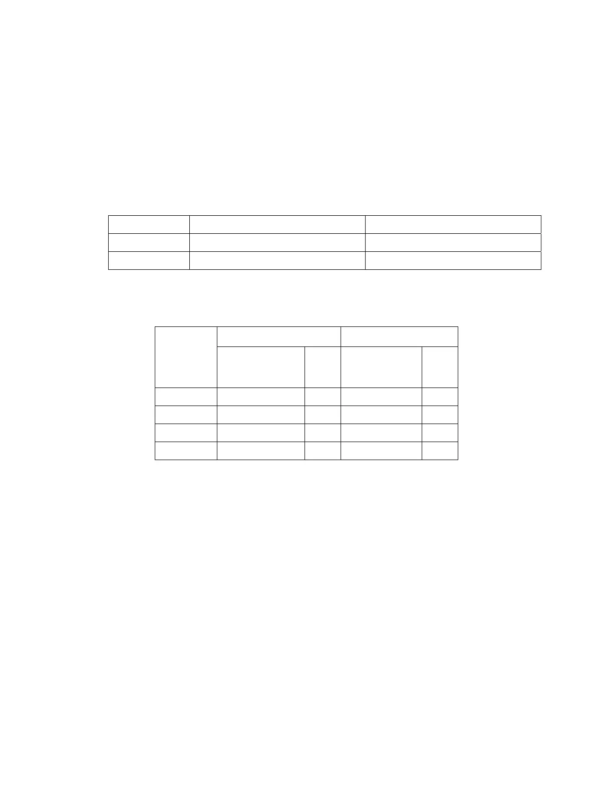
Table 2-4 Antenna Specifications – Selected radios
2.3 Locating Horizon Compact Antennas
In addition to ensuring that you have a clear line of sight (LoS) between antennas and that there are no
obstructions encroaching into the Fresnel zone, you must pay attention to the location of antennas
relative to objects located close by.
The antenna must be positioned in such a manner as to ensure that obstacles in close proximity to the
antenna do not interfere with the near field RF radiation from the antenna (near field effects). Close
proximity obstacles can cause reflections and severe interference with communications between radios.
This is especially critical for the 24 GHz Unlicensed frequency band, where radios are cross polarized.
Transmit signal reflections change polarity and can be “swallowed” by the receiver, causing swamping
and poor quality reception.
Note that the edge of a roof (roof line) must be considered an obstacle.
Table 2-5 shows the minimum antenna height requirements above obstacles for the 24 GHz Unlicensed
frequency band.
18 GHz Horizon 23 GHz Horizon
Antenna
Size
Beamwidth of
main lobe
(degrees, 3 dB)
Gain
dBi
Beamwidth of
main lobe
(degrees, 3 dB)
Gain
dBi
30 cm/12” 3.0 degrees 34 2.7 degrees 35.1
60 cm/24” 2.0 degrees 38.6 1.7 degrees 40.2
90 cm/36" 1.3 degrees 42.0 1.1 degrees 43.7
120 cm/48” 1.0 degrees 44.5 0.8 degrees 46.2