DragonWave Inc. 96
Horizon Compact Release 1.01.00 Wireless Ethernet Product User Manual – Volume 2
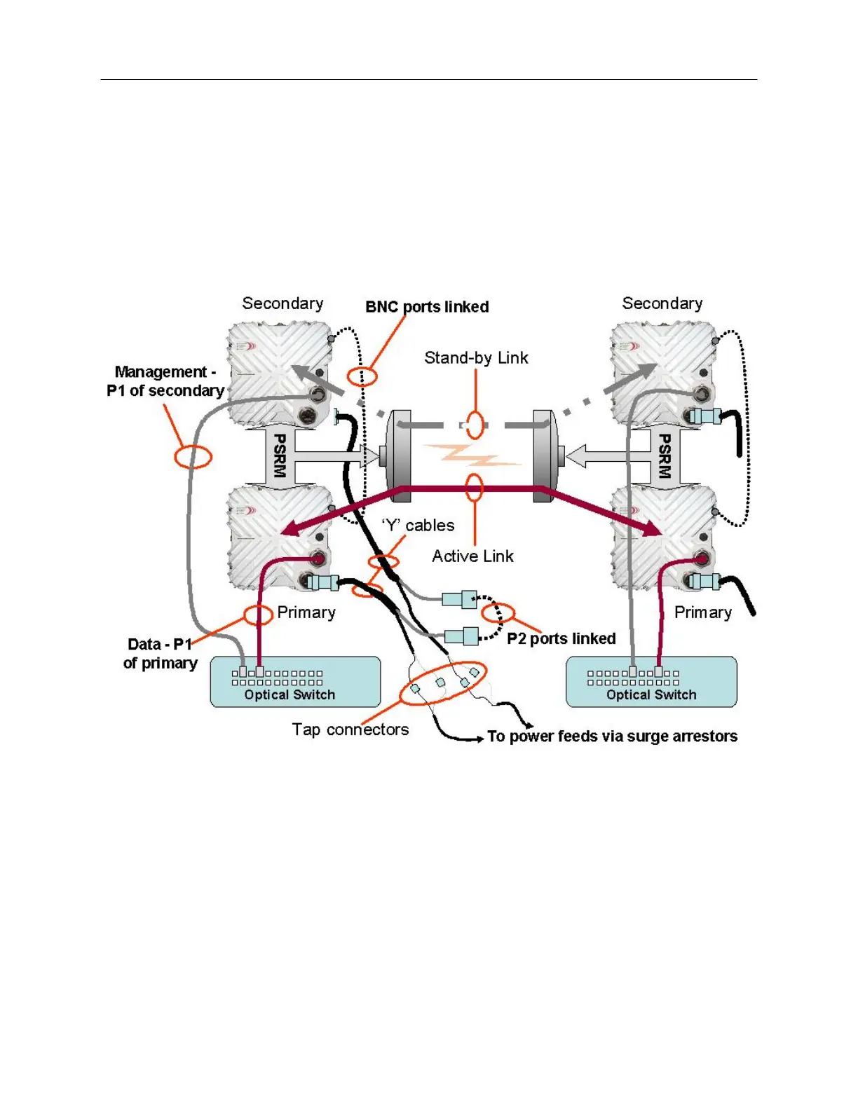
The Horizon Compact with optical interface is connected as shown in Figure 3-7.
NOTE: For clarity, the Transtector surge arrestor has been omitted from the diagrams. Both the
Port 2 Ethernet connections and the power feed via Port 2 must be protected from transients.
Figure 3-7 Redundancy Connections – single wire option – optical interface
The optical data feed is connected to Port 1 (P1) of the Primary unit and management is fed to Port 1 of
the Secondary unit. The Port 2 (P2) connection (weatherproof MIL type connector) is fed via a ‘Y’ cable
that splits out the power supply feed to the Horizon and an Ethernet cable using an in-line RJ-45
connector. The in-line RJ-45 connectors are linked, which interconnects Port 2 of both units. Power is fed
to the ‘Y’ cable using Tap connectors to join to the power feed cable having a suitable gauge for the
length of cable run employed.