Advanced Configuration Features
89
Horizon Compact Release 1.01.00 Wireless Ethernet Product User Manual – Volume 2
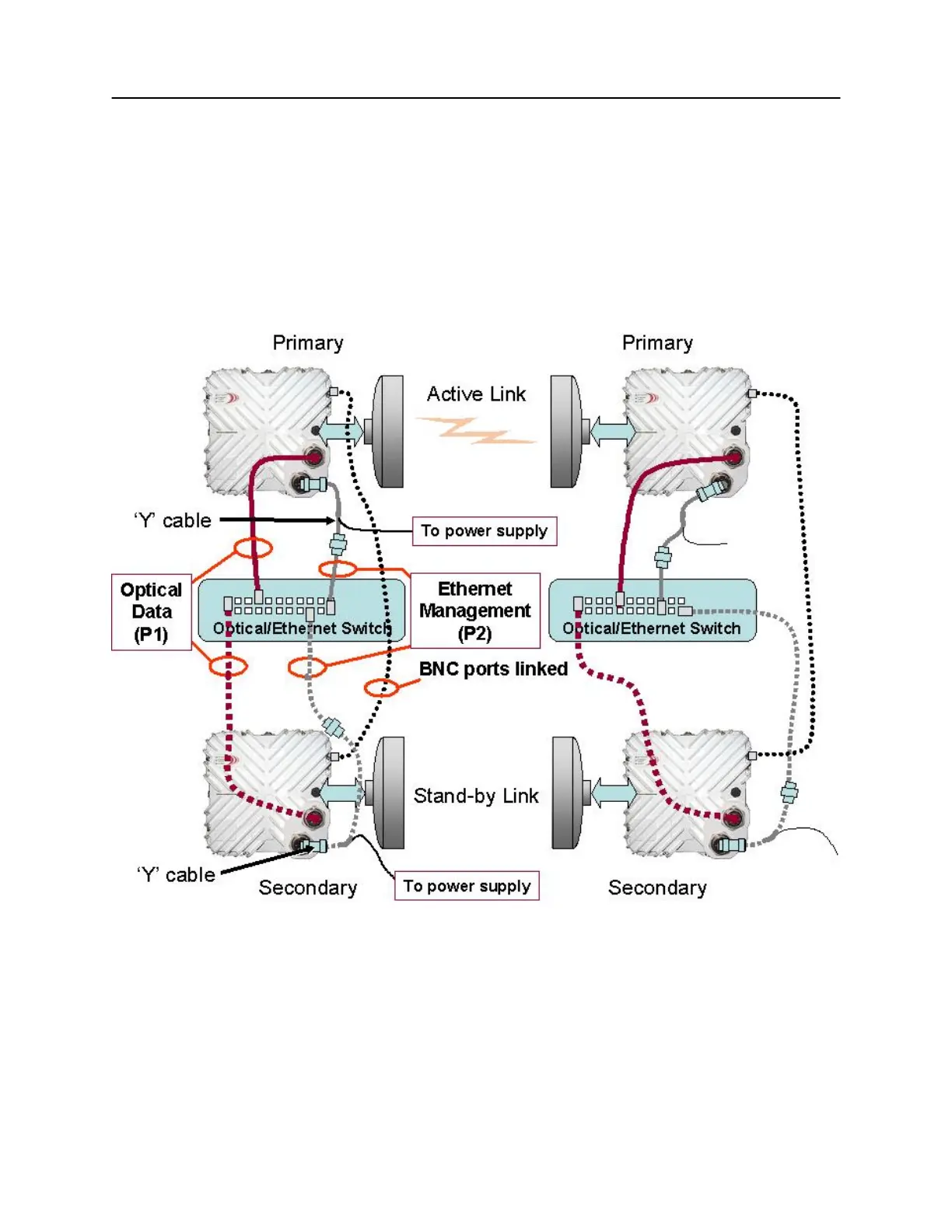
The Horizon Compact system with optical interface is connected as shown in Figure 3-4. Each end of the
link is connected the same way.
NOTE: For clarity, the Transtector surge arrestor has been omitted from the diagrams. Both the
Port 2 Ethernet connections and the power feed via Port 2 must be protected from transients.
Figure 3-4 Redundancy Connections – 2 wire option – optical interface
The optical data feeds are connected to Port 1 (P1) of both the Primary and Secondary horizon units, and
the optional out-of-band management is via Ethernet to Port 2 (P2) of both units. The Port 2 connection
(weatherproof MIL type connector) is fed via a ‘Y’ cable that splits out the power supply feed to the
Horizon and the optional management Ethernet feed (maximum length 100 m) using an in-line RJ-45
connector. Alternatively, the AirPair ODU composite power and Ethernet cable can be used for the Port 2
connection.