5-13
CH 5/ Start Menu
Circuit Setup
(continued)
Action... Result...
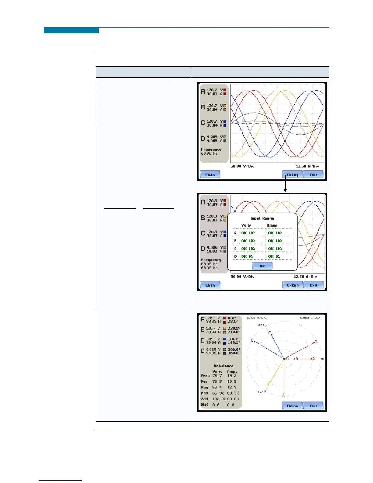
STEP 2: Scope mode allows users
to verify if waveforms look
correct for the specified wiring
setup.
• To check input range, press
CkRng. The Input Range
screen displays the detected
range for voltage and current
channels A, B, C, and D.
• The instrument registers a
message on the Input Range
screen that corresponds to the
detected input range for each
channel:
• When done checking the input
range, press OK to return to the
Scope mode screen. Once in
Scope mode screen, press Exit
to return to Circuit Type
Selection screen.
MARK201
MARK205
STEP 3: Phasor display shows a
graph that indicates phase
relations between voltage and
current.
For more information on phasors,
refer to Chapter 3 View Real
Time Data - Section D Voltage
and Current Phasor.
•Press Demo to show animated
phasor rotations.
•Press Exit to return to Circuit
Type Selection screen.
MARK241
Input Range
OK
OVER
UNDER
N/A
CLIP
Description
Within Range
Over Range
Under Range
Channel Disabled
Clipping
www.GlobalTestSupply.com
Find Quality Products Online at: sales@GlobalTestSupply.com
 Loading...