15
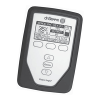
VAPOR-LOGIC
®
VERSION 6 INSTALLATION AND OPERATION MANUAL
Example: 12 mA – 4 mA
Calculation of transmitter % RH
INSTALLATION
x 100%
x 100% = 50% RH
Step 1 – Field wiring: Control input signals
MODULATING DEMAND SIGNAL CONTROL
With modulating demand signal control, a modulating humidistat
or a building automation system sends a signal to the Vapor-logic
controller, which then sends a signal to the humidifier to produce
a directly proportional steam output. For example, if a humidistat
operating between 4 mA and 20 mA sends a 4 mA signal,
the humidifier produces no output; a 12 mA signal causes the
humidifier to run at 50% of capacity; and a 20 mA signal causes
the humidifier to run at 100% capacity.
With a humidistat provided by DriSteem producing this signal, the
humidity set point is set at the humidistat. The display then is used
for maintaining and troubleshooting the humidification system,
with humidifier control stemming from the humidistat itself. With a
building automation system (BAS) providing the signal, the humidity
set point is established by the BAS, and the humidifier responds to
the BAS commands.
16 mA
TRANSMITTER CONTROL
With transmitter control, the Vapor-logic board receives a signal
that corresponds to the actual humidity level measured in the space
being controlled. (With a transmitter provided by DriSteem, the
signal is 4 to 20 mA, which corresponds to 0 to 100% RH). The
Vapor-logic controller employs an internal PID loop that uses this
humidity measurement along with a user-defined humidity set point
to calculate a demand level. This demand level is the level at which
the humidifier will run. See “PID tuning” on Page 49.
% RH =
(mA reading) – 4 mA
16 mA