10
VAPOR-LOGIC
®
VERSION 6 INSTALLATION AND OPERATION MANUAL
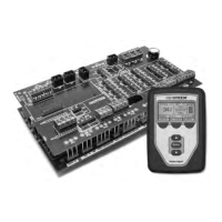
The Vapor-logic board is designed to make installation very easy:
• Terminal blocks that require field connections are outlined in white.
• Terminal plugs can be removed to allow easy access when inserting wires
and tightening screws.
• For most applications, humidifiers ship with the control board fully
configured, with drain, fill, and other humidifier components factory-wired
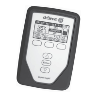
to the board, and the display attached to the humidifier and connected to
the Vapor-logic board.
SETUP OF VAPOR-LOGIC IS A THREE-STEP PROCESS:
1. Connect field wiring from device to Vapor-logic board.
See instructions beginning on Page 12. Note that some connections
listed here may not apply to your system.
• Control input (one required)
• RH or dew point transmitter
• Demand signal by others (4-20 mA or 0-10 VDC typical)
• Room or duct humidistat
• Demand signal by BACnet, Modbus, or LonTalk
• Limit controls
• Airflow switch (duct or SDU)
• Duct high limit on-off switch or transmitter
• Temperature compensation transmitter (or auxiliary temperature
sensor connected to same terminal)
• Master enable
Installation process
INSTALLATION