12
VAPOR-LOGIC
®
VERSION 6 INSTALLATION AND OPERATION MANUAL
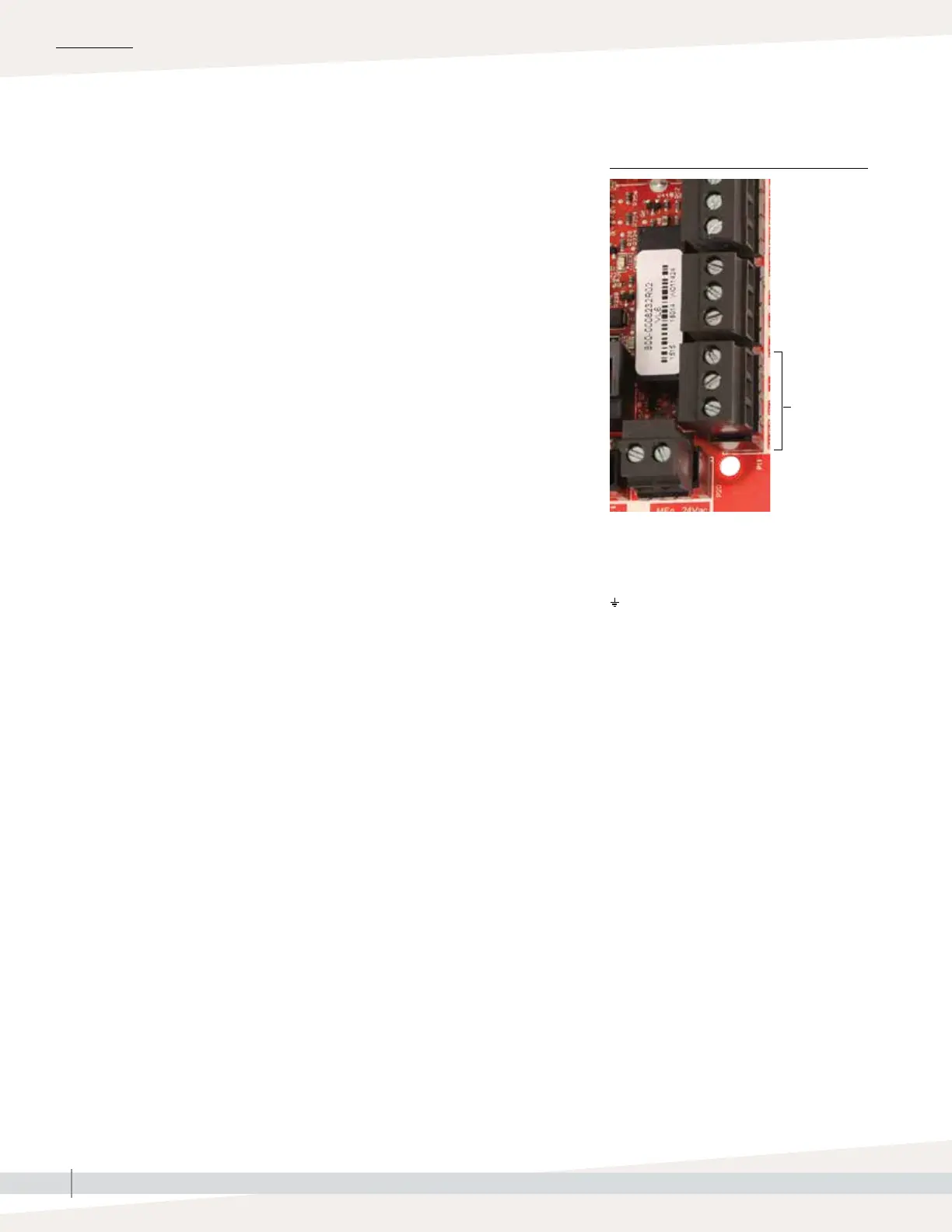
Step 1 – Field wiring:
Terminal P11:
21vdc = Power to space RH sensor
RH = Space RH input (RH transmitter, dew point
transmitter, humidistat, or demand signal
by others (4-20 mA or 0-10) VDC input
= Ground for demand signal by others
Terminal P11
Note:
If you do not know which control components
were ordered with your system, contact
DriSteem or connect your display to the Vapor-
logic board per the instructions on Page 19.
Go to the instructions on Page 27 to view
system parameters that were factory configured
as ordered.
INSTALLATION
Control input
FIGURE 12-1: TERMINAL P11
Connect control input signal wiring by inserting wires into Terminal P11
(labeled 21vdc, RH, and ground) per the wiring diagram on the next page.
Tighten screws.
Allowed inputs at Terminal P11 include:
• RH transmitter or dew point transmitter
Transmitters provide a signal proportional to the RH or dew point being
measured. All transmitters provided by DriSteem are two-wire devices using
a 4 to 20 mA signal.
• Demand signal by others
Demand signals are sent to the Vapor-logic board from another control
system such as a building automation system. These systems have their own
RH or dew point transmitters, calculate required humidifier output, and send
a demand signal to the humidifier to create steam at a percentage of that
humidifier’s capacity. Demand signals are typically 0-10 VDC or 4-20 mA,
but may also come from a DDC signal via Modbus, BACnet, or LonTalk.
• A humidistat also delivers a demand signal to the humidifier, but it is not
typically used with Vapor-logic.
Humidistats provide either on-off control or modulating control. DriSteem
humidistats are powered by a 24 VDC supply provided by the Vapor-logic
control board.
When using modulating control, the signal from a humidistat directly
controls the amount of output from the humidifier.
Notes:
• See Figure 13-1.
• For more information about control input signal types and operation, see
"On-off control" on page 14.
• See "Modbus, BACnet, LonTalk interoperability" on page 66 for more
information about input signals.