8
VAPOR-LOGIC
®
VERSION 6 INSTALLATION AND OPERATION MANUAL
Pre-installation Checklist
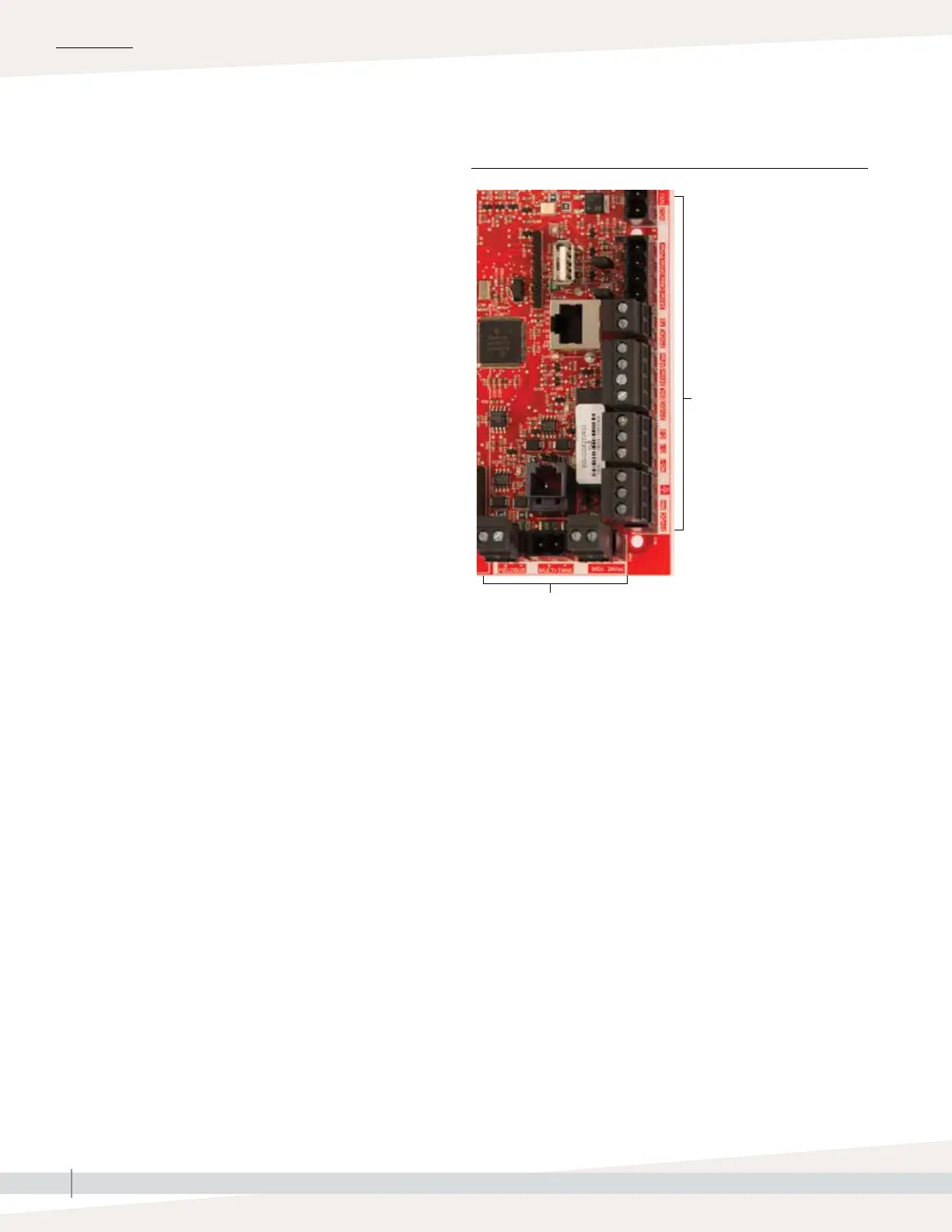
☐ See Figure 8-1 for field terminal block locations. Note
that field wiring connection locations on the Vapor-logic
board are surrounded with a white border.
☐ See the figure on the next page for instructions on how
to make wiring connections.
☐ See the wiring drawings and manuals that shipped
with your humidifier.
☐ When making field connections, do not route low
voltage wires near line voltage wires. Do not route low
voltage wires in the same conduit as line voltage wires.
☐ Humidistat, room/duct transmitter, temperature sensor,
and airflow proving switch wiring must be minimum
18-gauge (1 mm
2
) plenum rated, shielded (screened),
twisted pair wire with a bare drain wire for grounding.
☐ Connect the shield (screen) wire [with a length less than
2" (50 mm)] to the shield (screen) ground terminal on
the electric subpanel. Do not ground the shield (screen)
wire on the humidistat or transmitter end.
Board detail showing white border
Field connection terminals.
Terminals P-11 through P-16
have a white border on the
Vapor-logic board. This is
where you will make most of
your field wiring connections.
INSTALLATION
Field connection terminals.
FIGURE 8-1: VAPOR-LOGIC CONTROL BOARD DETAIL