4
VAPOR-LOGIC
®
VERSION 6 INSTALLATION AND OPERATION MANUAL
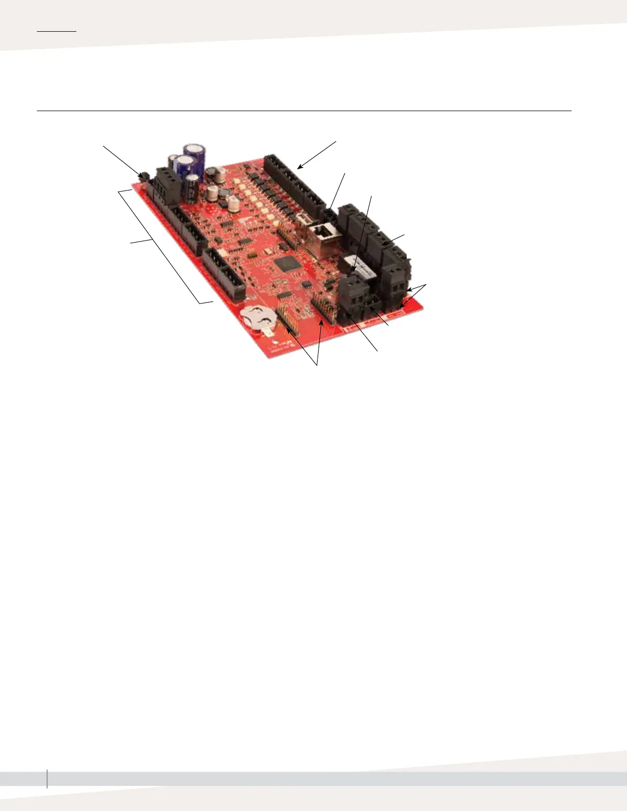
Vapor-logic board
The photo above shows key components of the Vapor-logic control board. See the illustration on the next page for more detail.
Power connection
Factory connection points for drain, fill, etc.
Field connection points for transmitters,
airflow switch, etc.
Connection pins for optional LonTalk module
Display connection
BACnet or Modbus connection
Factory connection points
for water level control,
gas valves, etc.
Multi-tank connection
OVERVIEW
Ethernet connection for computer network and/or BACnet/IP
Field connection terminal labels
(white border)
FIGURE 4-1: VAPOR-LOGIC CONTROL BOARD
: Components