13
VAPOR-LOGIC
®
VERSION 6 INSTALLATION AND OPERATION MANUAL
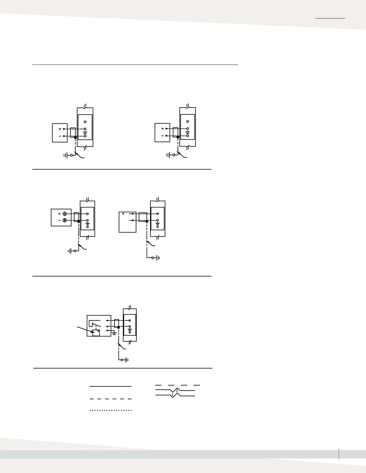
Signal by others
Transmitter
On-o RH humidistat
Room/Duct humidistat
INSTALLATION
0-10 VDC
Vapor-logic
21VDC
RH
2-wire #18GA
Shield cable
Control panel
shield GND lug
4-20 mA
Vapor-logic
Input resistance
500 ohms
21VDC
RH
2-wire #18GA
Shield cable
Control panel
shield GND lug
2-wire #18GA
Shield cable
Control panel
shield GND lug
2-wire #18GA
Shield cable
Control panel
shield GND lug
RH
Dew point
Vapor-logic
Vapor-logic
P11 P11
Room
or duct
RH
Y
21VDC
RH
21VDC
RH
21VDC
4-20 mA humidity
sensor
COM
Note: Input resistance 500 ohms
Note:
Input resistance on 4-20 mA is 500 ohms
2-wire #18GA Shield cable (TYP)
Control panel shield GND lug
% H20
Room or duct
NC contact
opens above set
point
21VDC
RH
NC
C
GN
P11
Control circuit wiring
Field wiring
Optional factory
Optional field
Break to external
connections diagram
Key
Step 1 – Field wiring: Control input
FIGURE 13-1: VAPOR-LOGIC CONTROL INPUT WIRING CONNECTIONS