19
VAPOR-LOGIC
®
VERSION 6 INSTALLATION AND OPERATION MANUAL
VAPOR-LOGIC DISPLAY
If your display is factory-mounted and connected to the Vapor-logic board,
proceed to installing the next device required by your system.
If your display was shipped loose, mount the display in a location so that the
provided cable is long enough to connect the display to the Vapor-logic board.
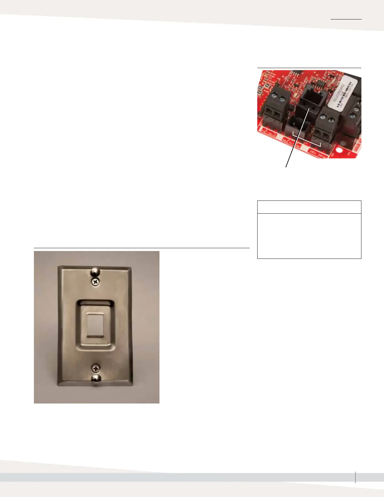
To connect a Vapor-logic display to the Vapor-logic board, insert one end of the
provided cable into the Vapor-logic board at Terminal P10 (labeled Display)
until you hear a click sound (see also the wiring diagram on the next page).
Plug the other end of the cable into the display. This connection provides DC
power and communication to the display.
See Caution at right before routing cable.
If a longer display cable is needed, order a replacement cable from DriSteem
(see the replacement parts section of this manual), or use a four-conductor
straight-through cable or a six-conductor, crossover, twisted pair cable
connected to an RJ11 jack.
Note required operating conditions listed on Page 3.
Terminal P10:
Display
INSTALLATION
CAUTION
Touchscreen display cable
Maximum cable length is 500’ (152 m).
When routing display cable, route
cable away from all power wiring.
Step 1 – Field wiring: Communication connections
FIGURE 19-1: TERMINAL P10
FIGURE 19-2: MOUNT THE TOUCHSCREEN DISPLAY ON A WALL
USING THE WALL PLATE