18
VAPOR-LOGIC
®
VERSION 6 INSTALLATION AND OPERATION MANUAL
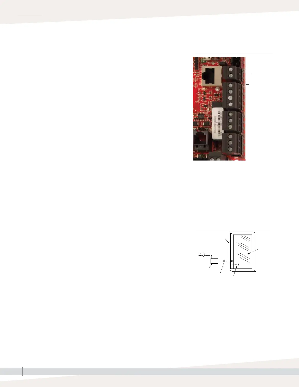
Terminal P14
Terminal P14:
21vdc = Power to auxiliary temperature sensor
or temperature compensation sensor
(transmitter)
TS = Auxiliary temperature sensor or
temperature compensation sensor
(transmitter) (4-20 mA input)
OM-337
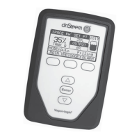
Thermostat
control wires
Surface-
mounted
thermostat
temperature
control box
on wall
Typical
sensor
cord
routing
Secure temperature
sensor tip to inside
surface of window
glass using clear RTV
silicone adhesive
Double-
pane
window
glass
Window frame
INSTALLATION
Connect wiring for a temperature compensation transmitter or an auxiliary
temperature sensor by inserting wires into the terminal block plug at P14
(labeled 21vdc and TS) per the wiring diagram on the previous page. Tighten
screws; maximum torque is 3 in-lb (0.34 N-m).
Note: Only one device can be connected at P14. You will identify the
connected device in “Step 2 – Setup,” beginning on Page 27.
AUXILIARY TEMPERATURE SENSOR
An auxiliary temperature sensor typically monitors duct or space air
temperature. Mount the auxiliary temperature sensor wherever you want to
monitor temperature. Auxiliary temperature readings are logged to the data
log.
TEMPERATURE COMPENSATION TRANSMITTER
A temperature compensation transmitter allows Vapor-logic to reduce humidifier
output on cold days, reducing window condensation. Mount the temperature
compensation transmitter on the inside of an outside-wall window.
To mount the temperature compensation sensor:
1. See Figure 18-2. Position the temperature compensation sensor control box
on a wall adjacent to a window frame facing north or northeast.
2. Place the flat surface of the temperature sensor tip on the lower corner of
glass surface.
3. Temporarily hold the sensor tip in place with strips of masking tape.
4. Apply a small amount of clear RTV silicone adhesive over and around the
sensor tip (making sure the sensor tip is in contact with the window glass).
5. After adhesive cures, remove masking tape.
6. See the operation section of this manual for more information about the
temperature compensation sensor.
FIGURE 18-1: TERMINAL P14
Step 1 – Field wiring: Limit controls
FIGURE 18-2:
TEMPERATURE COMPENSATION
TRANSMITTER INSTALLATION