3 INSTALLATION
The DSEGateway
®
is designed to be mounted within a control panel, either on the panel DIN rail
utilising the integral mounts, or chassis mounted, utilising the mounting holes. For dimension and
mounting details, see the section entitled Specification, Dimensions elsewhere in this document.
3.1 USER CONNECTIONS
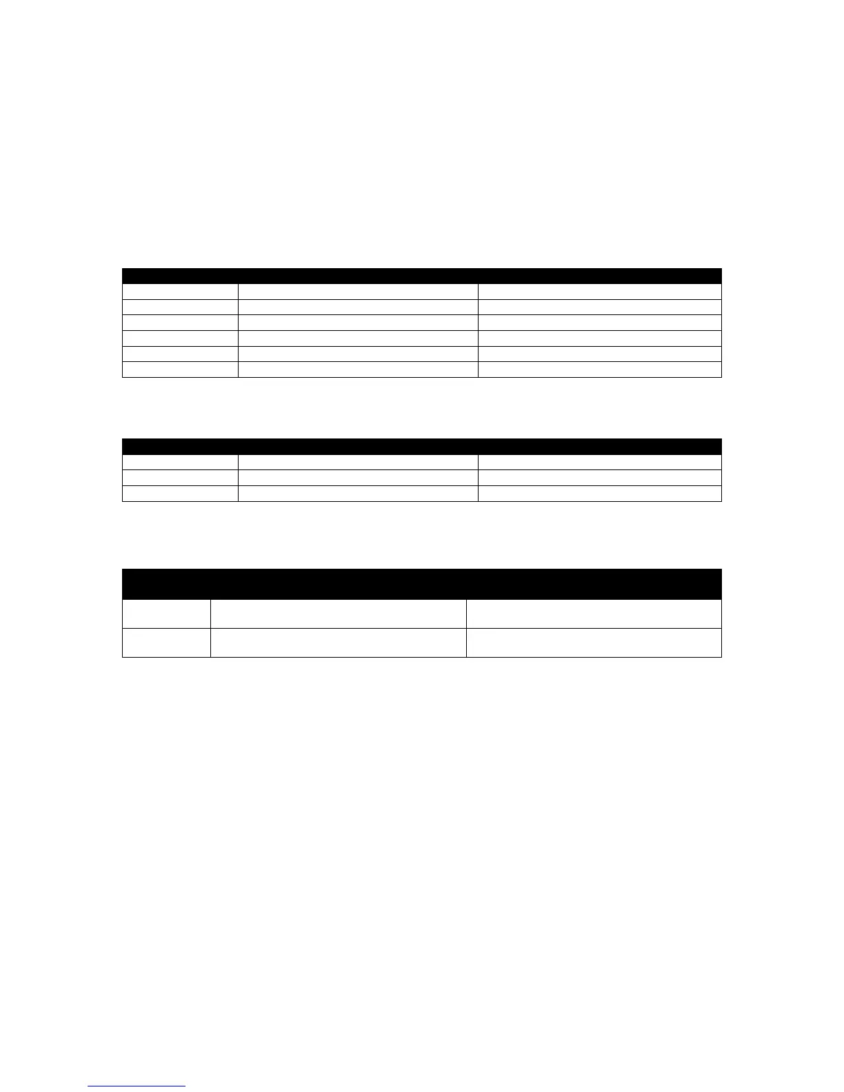
3.1.1 CONNECTOR A – DC SUPPLY AND CONFIGURABLE OUTPUTS
Configurable Input / Output (I/O)
Configurable Input / Output (I/O)
Configurable Input / Output (I/O)
Configurable Input / Output (I/O)
3.1.2 CONNECTOR B – RS485
3.1.3 GSM & GPS CONNECTIONS (DSE890 3G GATEWAY ONLY)
Required Antenna Cable Connector
SMA FEMALE
(Outside thread, female central receptacle)
SMA MALE
(Inside thread, male central pin)
SMA MALE
(Inside thread, male central pin)
SMA FEMALE
(Outside thread, female central receptacle)