This is the port that is connected to the DSE controller.
RS232: Connection to a single controller via RS232 NULL Modem (crossover)
cable with female 9 pin D connector terminations.
RS485: Connection to one or more RS485 enabled controllers using suitable
RS485 connection cable.
Ethernet: Connection to an Ethernet network of one or more controllers.
USB: Single connection to a supported DSE controller by USB A – USB B
cable.
NOTE: RS485 is a single master system. This means that only one
entry must be created for RS485 in the Slave column. Each entry in the
Master column must communicate with controllers with unique Slave
ID’s.
NOTE: RS232 is a single master, single slave system. This means
that only one entry must be created for RS232 in the Master and Slave
columns.
NOTE: Where multiple Ethernet connections are configured, each
must utilise a unique port number.
When Port is set to Ethernet – TCP port to use for Modbus (usually 502).
When Port is set to RS232/RS485 – Baud rate of the selected controller.
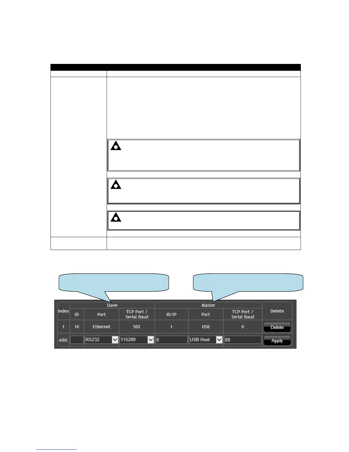
5.5.3.3 EXAMPLE OF MODBUS GATEWAY SETTINGS.
Index 1 is receiving modbus requests from the external monitoring system on Ethernet, TCP Port
502.
This is being transferred to the DSE controller via the USB Host port on the DSEGateway
®