■■■■■■■■■■■■■■■■■■■■■■■■■■■■■■■■■■■■■■■■■■■■■■■■■■■■■■■■■■■■■■■■■■■■■■■■■■■■
▼
Signal Connection to External Devices
DS1104 Hardware Installation and Configuration March 2004
141
▲
■■■■■■■■■■I
▲■■■■■■■■■■■■■■■
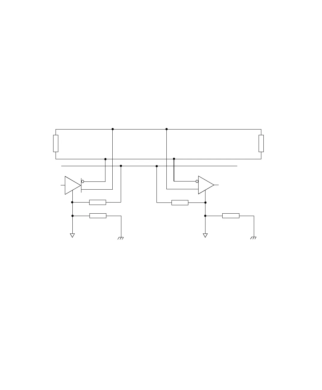
Ground connection For correct operation of the transmitter and the receiver, a return
signal path between the grounding of the individual devices is
required.
This has to be realized by a third wire. Here a resistor can be connected
in series to limit unwanted high currents resulting from ground
potential differences.
The figure below shows the grounding arrangement in an RS485
network.
Z
T
Z
T
100
Ω
100
Ω
100
Ω
100
Ω
Ground wire
Logic ground
Chassis groundChassis ground
Logic ground
T = Transmitter
R = Receiver
T
R