63 … 68
62 … 68
Printed in Germany • Edition 02.14 • Nr. 254 722
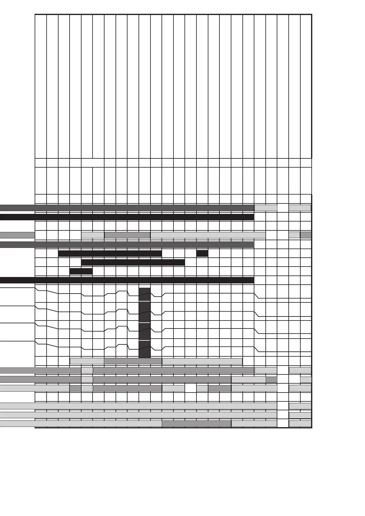
15 Time diagram
MPA51xx
by means of an extended module
General version
Viessmann version
Error
Waiting for heat request
Waiting for parameter record stick adjustment
Idle state control: Fan/stepped motor
Idle state control LDW (air pressure switch)
Watchdog loading phase
Startup phase: Fan/stepped motor
Waiting for air pressure
VPS A: Decision
VPS A : Emptying the area between the valves
VPS A: Test time V1
VPS A: Filling the area between the valves
VPA A: Gas pressure detection
VPS A: Test time V2
Pre-aeration A
Parameter
P40 P42 P43 P44 P45 P60
Time
0...
0...
max. 3 min
max. 2 min
max. 2 min
3 s
max. 2 min
max. 30 s
0.1 s
1...3 s
1...240 s
1...3 s
0.1 s
1...240 s
0...1 h
State number
0 1 2 3 4 5 6 7 8 9 10 11 12 13 14
Safety chain
Watchdog
Alarm
Temperature controller
Additional valve *4
Y1 Y3
V1
Y2 Y1
V2
Y3 Y2
Ignition
Fan relay
PWM1 (fan)
*2a
*2b
PWM2 (for ex. analogue 0...10 V)
● *2a
*2b
PWM3 (for ex. analogue 4... 20 mA)
● *2a
*2b
Stepped motor
● *2a
*2b
Flame (ionisation)
LDW *1
GDW min.
GDW VPS *5
Parameter record stick active
●
Parameter VPS Startup
Parameter VPS Regular switch-o
Pre-aeration B
Ignition position
Gas detection GDWVPS
Pre-ignition
SZA ignition
SZA - Flame detection
Stabilisation ame A
Stabilisation ame B
Changeover to the standard mode
Standard mode
Changeover after regular switch-o
VPS B: Decision
VPS B : Emptying the area between the valves
VPS B: Test time V1
VPS B: Filling the area between the valves
VPA B: Gas pressure detection
VPS B: Test time V2
Follow-up time
Post-aeration
Restart protection
Waiting for heat request
Lack of gas GDWMIN
Waiting program
P61 P62 P63 P64 P65 P66 P70 P80 P41 P42 P43 P44 P45 P82 P83 P84 *3
0...1 h
max. 2 min
0...1 h
0...1 min.
0.5...9, 4 s
0.5 s
1...200 s
1...200 s
max. 2 min.
0...
1...30 s
0.1 s
1...3 s
1...240 s
1...3 s
0.1 s
1...240 s
1...60 s
0...1 h
0...1 h
0...
0...
x min.
15 16 17 18 19 20 21 22 23 24 25 26 27 28 29 30 31 32 33 34 1 35 36
*2c *2d *2e *2f *2g *2h *2i *2j
*2a
*2c *2d *2e *2f *2g *2h *2i *2j
*2a
*2c *2d *2e *2f *2g *2h *2i *2j
*2a
*2c *2d *2e *2f *2g *2h *2i *2j
*2a
goes to the fault switch-o. The waiting pro-
gram state is triggered by a lack of gas or an
open safety chain.
*4) The start help valve can be switched on
and o at any time (parameter). However it
must be activated with the beginning of the
state "Waiting for gas pressure" at the earli-
est and during the valve test after a regular
switch-o at the latest.
*5) The GDW VPS is monitored during the
valve test. Additionally, the parameter P46
can dene whether the minimum pressure
monitoring via GDWVPS during operation
between state 17 and state 25 is active or not.
*6) The ame is detected here and must be
generated in this state at the latest.
*6