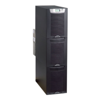
Eaton® 9390 (100–160 kVA) UPS Installation and Operation Manual 164201604—Rev F 110
99..11..1166 TTrraannssffeerr ffrroomm NNoorrmmaall ttoo BByyppaassss MMooddee aanndd SShhuutt DDoowwnn UUPPSS
To transfer the critical load to Bypass mode and shut down the UPS:
1. Transfer the critical load to bypass by performing the procedure in
9.1.4 Transfer from Normal to Bypass Mode.
2. Press the CCOONNTTRROOLLSS pushbutton on the main menu bar. The System Control screen appears.
3. Press the
USING THE CONTROL PANEL
Eaton 9390 UPS (20–80 kVA) and 9390IT (20-40 kVA) Installation and Operation Manual S 164201603 Rev 4
8-15
Select TIME INTERVAL MONITORED from the Current kW Demand Log Setup screen 2
menu to display the Time Interval Monitored Setup screen. The Time Interval
Monitored Setup screen allows the time duration of the event being monitored to be
changed. Figure 8‐17 shows the Time Interval Monitored Setup screen.
Use the
or pushbuttons to select the character position. Use the or
pushbuttons to change the character value. Once the new value is entered, press the
DONE pushbutton. The Time Interval Monitored Setup Save screen is displayed.
0000
DONE
TIME INTERVAL MONITORED SETUP
Figure 8‐17. Time Interval Monitored Setup Screen
The Time Interval Monitored Setup Save screen lets you save the new time interval,
retry another time interval, or abort the change. Figure 8‐18 shows the Time Interval
Monitored Setup Save screen.
Press SAVE, RETRY, or ABORT. If SAVE or ABORT is pressed, the action is completed,
and the Current kW Demand Log Setup screen 2 displays. If RETRY is pressed, the
Time Interval Monitored Setup screen is redisplayed.
ABORT
SAVE RETRY
0000
TIME INTERVAL MONITORED SETUP
Figure 8‐18. Time Interval Monitored Setup Save Screen
pushbutton to display System Controls Screen 2.
4. Press the PPMM OOFFFF pushbutton on the System Controls menu bar.
The power module (PM) status indicates SHUTDOWN. The input and output contactors open, the battery
breaker or disconnect is tripped, and the power module is turned off. The bypass source supplies the
critical load.
Power is present inside the UPS cabinets.
99..11..1177 UUPPSS aanndd CCrriittiiccaall LLooaadd SShhuuttddoowwnn
To perform maintenance or service on the critical load, shut down power to the load by performing the
following procedure:
1. Turn off all equipment that is being powered by the UPS.
2. Perform the LOAD OFF procedure in 9.1.19 Using the UPS LOAD OFF Pushbutton.
The input, output, and bypass backfeed contactors open, the battery breaker or disconnect is tripped, and
the power module is turned off.
Power is present inside the UPS cabinet until the upstream input feeder circuit breaker is opened.
3. Open the UPS input and bypass (if dual feed) feeder circuit breakers.
99..11..1188 CChhaarrggeerr CCoonnttrrooll
To turn the battery charger on or off:
1. Press the CCOONNTTRROOLLSS pushbutton on the main menu bar. The System Control screen appears.
2. Press the
USING THE CONTROL PANEL
Eaton 9390 UPS (20–80 kVA) and 9390IT (20-40 kVA) Installation and Operation Manual S 164201603 Rev 4
8-15
Select TIME INTERVAL MONITORED from the Current kW Demand Log Setup screen 2
menu to display the Time Interval Monitored Setup screen. The Time Interval
Monitored Setup screen allows the time duration of the event being monitored to be
changed. Figure 8‐17 shows the Time Interval Monitored Setup screen.
Use the
or pushbuttons to select the character position. Use the or
pushbuttons to change the character value. Once the new value is entered, press the
DONE pushbutton. The Time Interval Monitored Setup Save screen is displayed.
0000
DONE
TIME INTERVAL MONITORED SETUP
Figure 8‐17. Time Interval Monitored Setup Screen
The Time Interval Monitored Setup Save screen lets you save the new time interval,
retry another time interval, or abort the change. Figure 8‐18 shows the Time Interval
Monitored Setup Save screen.
Press SAVE, RETRY, or ABORT. If SAVE or ABORT is pressed, the action is completed,
and the Current kW Demand Log Setup screen 2 displays. If RETRY is pressed, the
Time Interval Monitored Setup screen is redisplayed.
ABORT
SAVE RETRY
0000
TIME INTERVAL MONITORED SETUP
Figure 8‐18. Time Interval Monitored Setup Save Screen
pushbutton to display System Controls Screen 2.
3. Press the CCHHGGRR OONN or CCHHGGRR OOFFFF pushbutton on the System Controls menu bar to toggle the charger on
or off.
99..11..1199 UUssiinngg tthhee UUPPSS LLOOAADD OOFFFF PPuusshhbbuuttttoonn
A UPS Load Off is initiated by the LLOOAADD OOFFFF pushbutton from the main menu bar or the System Controls
menu bar. This pushbutton can be pressed to control the UPS output. The UPS LLOOAADD OOFFFF pushbutton de–
energizes the critical load and powers down the UPS.
The UPS (including Bypass) remains off until restarted.
To use the LLOOAADD OOFFFF pushbutton:
1. Press the LLOOAADD OOFFFF pushbutton.
The Load Off screen appears, providing a choice to proceed or abort the shutdown.
UPS Operating Instructions

 Loading...

