RACK−MOUNTING THE EPDU
EATON Managed ePDU User’s Guide 164201xxx Rev 1 DRAFT 10−OCT−2008
9
Mounting Instructions
The 0U models also ship with a tool−less mounting kit consisting of a claw feet with a
silver button on one side. These work by attaching to the back side of a 0U ePDU (the
side opposite of the outlets) and tting the button into the mounting holes of the
cabinet. Note that not all racks allow the option of securing the ePDU in this way.
Before beginning:
Ensure that you have sucient space in the cabinet to mount the ePDU.
Approximately one inch of clearance is required at each end (top and bottom) of
the ePDU.
It may help to mark the back of the ePDU through the mounting holes you intend
to use. You can then use this mark to assist in aligning the silver buttons properly
when attaching the claw−feet.
To mount:
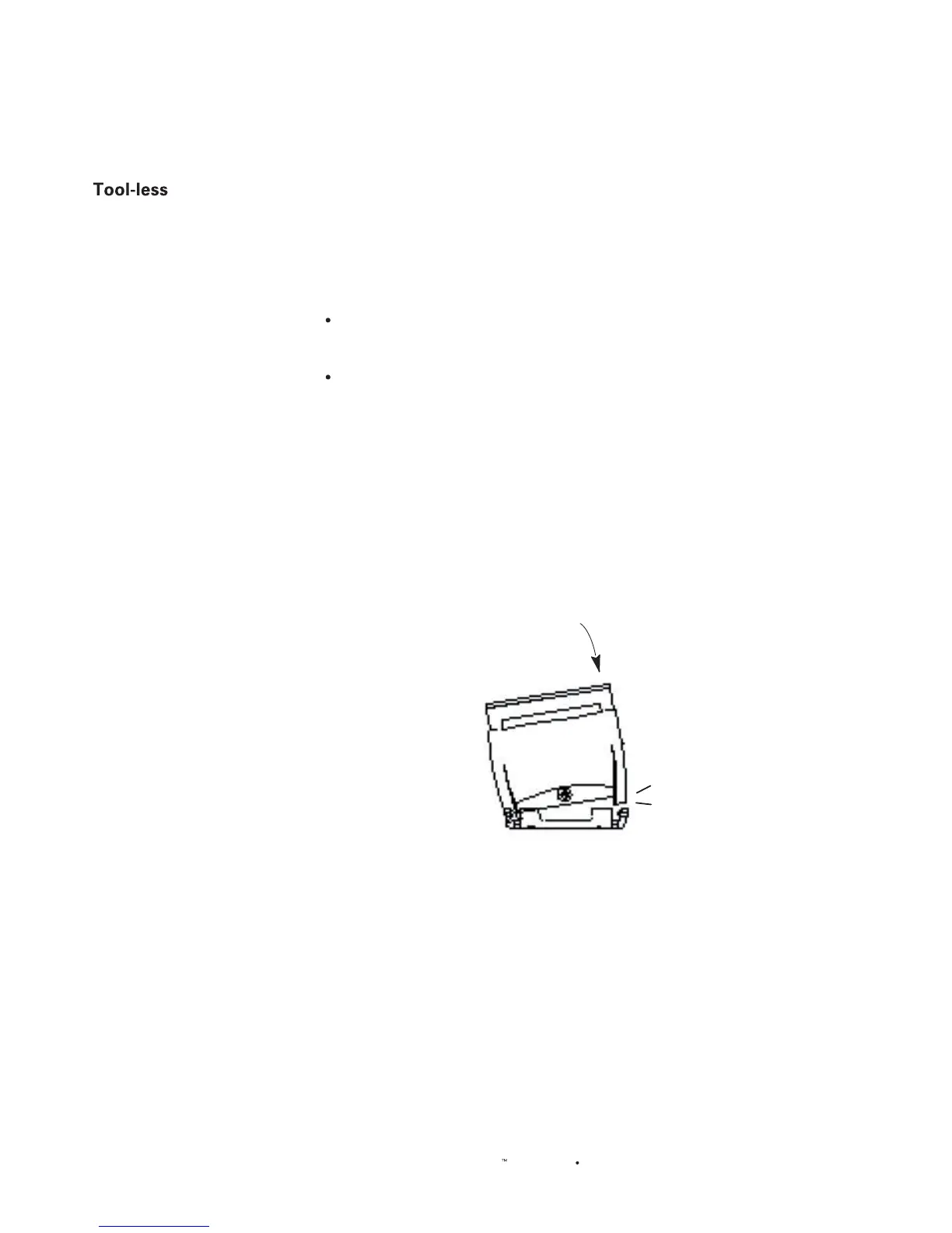
1. Snap t the claw feet mounts onto the back of the ePDU. Hook one side of the
ePDU body into one side of a claw foot rst, and then apply pressure to snap in
the second side. Figure 8 shows how rm pressure is applied to snap t the claw
feet to the ePDU 0U model.
Leave at least 610 mm between the buttons for stability. Once the claw feet
are mounted on the ePDU rail, they will not readily move. A at−head screwdriver
can be used to remove the feet if they need to be repositioned.
Firm Pressure
Click
Figure 8. Snap Fit to Claw Foot
2. Align the silver buttons with the mounting holes in the cabinet, and ensure that
both buttons can engage their mounting holes simultaneously.
3. Press the ePDU forward, pushing the silver buttons through the mounting holes,
then letting the ePDU drop about 16 mm. This secures the ePDU in
place and completes the installation.
 Loading...


