6 Parameter structure
6.6 Parameter
142 DC1-S…20…, DC1-S…OE1 Variable Frequency Drives 05/21 MN040058EN www.eaton.com
6.6 Parameter
The following tables use a number of acronyms. These acronyms are defined
below:
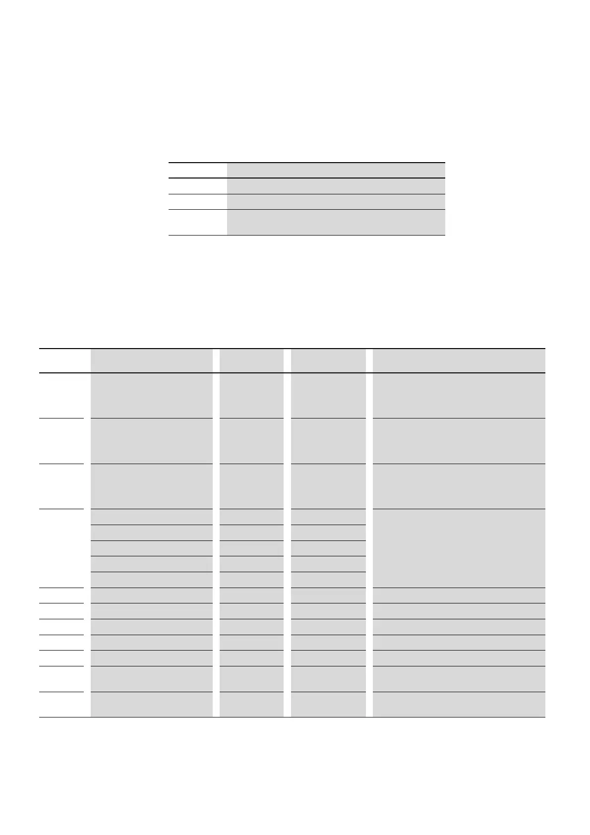
6.6.1 “Monitor” parameter group
Table 47: “Monitor” parameter group
Abbreviation
Meaning
Min. value Minimum value
Max. value Maximum value
DS
Default setting (the parameter’s value when using the device’s
factory settings)
→
None of the parameters in parameter group 0 can be modified
by the user, i.e., they are read-only parameters.
Parameter Designation min. value max. value Description
P00-01 Analog Input1 0 100% Analog Input 1
Level of the signal applied to analog input 1 after
scaling and offsets have been applied.
P00-02
Analog Input2 0 100% Analog Input 2
Level of the signal applied to analog input 2 after
scaling and offsets have been applied.
P00-03
Frequency Reference -P-01 P-01 Frequency Reference in Hz.
Will be calculated into rpm when motor data are
available.
Value of the drive internal digital reference.
P00-04
DI1 Status 0 1 State of digital inputs
Status of the digital inputs starting on the left hand
side with digital input 1 etc.
DI2 Status 0 1
DI3 Status 0 1
DI4 Status 0 1
DI5 Status 0 1
P00-05
PID1 Output 0 100 % PI(D) controller 1 Output
P00-06
DC-Link Voltage Ripple 0 1000 V DC-Link Voltage Ripple
P00-07 Motor voltage 0V 600 V AC Instantaneous output voltage
P00-08 DC Link Voltage 0V 1000 V DC Instantaneous DC Link Voltage
P00-09 Heatsink Temperature -20 °C 100 °C Instantaneous Heatsink Temperature
P00-10
t-Run 0 h 99999 h Total operating time of the drive since the date of
manufacture
P00-11
t-Run since Trip 0 h 65000 h Total operating time of the drive since the last trip
occurred

 Loading...


