3 Installation
3.3 Mount ing
DC1-S…20…, DC1-S…OE1 Variable Frequency Drives 05/21 MN040058EN www.eaton.com 51
3.3.3 Fixing
All DC1-S… variable frequency drive frame sizes can be mounted with
screws. Moreover, frame sizes FS1 und FS2 with an IP20 degree of
protection can be mounted on a mounting rail as well.
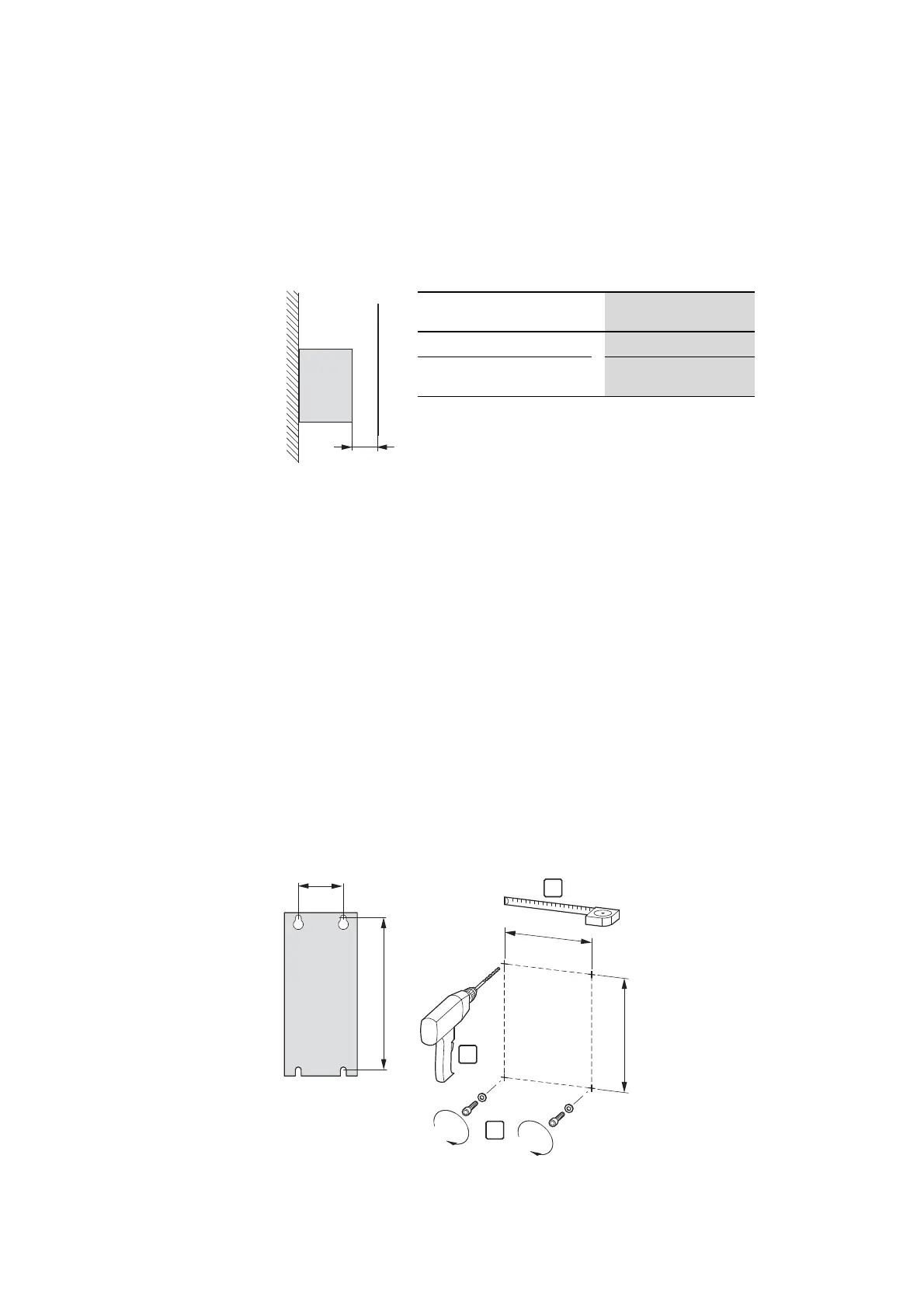
3.3.3.1 Fixing with screws
→
Typical heat loss makes up about 3% of the operational load
conditions.
Figure 23: Minimum required clearance ① in front of the
variable frequency drive when installed in an
enclosure (control panel)
Size with IP20 degree of
protection
Minimum clearance ①
FS1, FS2
≧ 15 mm (≧ 0.59 inch)
FS1, FS2 with DX-NET-SWD3
and SWD4-8SF2-5
≧ 50 mm (≧ 1.97 inch)
→
Dimension and weight specifications for the DC1-S… variable
frequency drive can be found in the → section 7.3,
“Dimensions”, page 164.
→
Use screws with a washer and split washer with the
permissible tightening torque in order to protect the enclosure
and safely and reliably mount the device.
Figure 24: Mounting dimensions
1
2
3
b1
a1

 Loading...


