3 Installation
3.7 Block diagrams
DC1-S…20…, DC1-S…OE1 Variable Frequency Drives 05/21 MN040058EN www.eaton.com 87
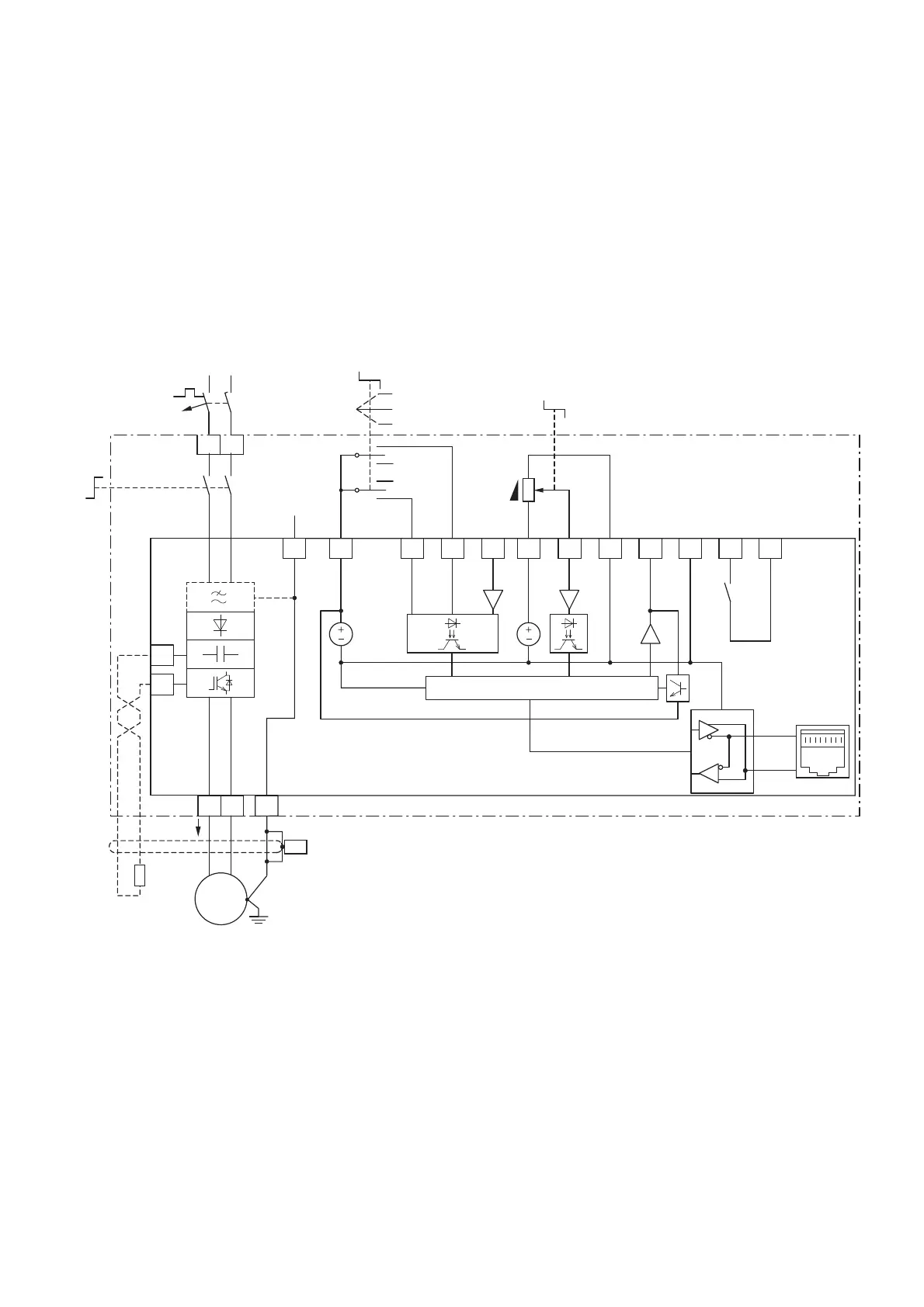
3.7.3 DC1-S1…-A6S…, DC1-S2…-A6S…
Mains voltage U
LN
:
DC1-S1…: single-phase, 110 (-10 %) - 115 (+10 %) V, 50/60 Hz
DC1-S2…: single-phase, 200 (-10 %) - 240 (+10 %) V, 50/60 Hz
Motor voltage U
2
: single-phase, U
2
= U
LN
, 0 - 50/60 Hz (max. 500 Hz)
Size: FS1 and FS2 with IP66 degree of protection
Figure 59: Block diagram DC1-S1…-A6S…, DC1-S2…-A6S…
Variable frequency drive with IP66 degree of protection, local controls,
single-phase mains supply voltage, and single-phase motor connection
2
DI1
24 V
3
DI2
NOT USED
FWD
4
DI3
AI2
5
+10 V Out
< 10 mA
10 V
6
AI1
DI4
f-Soll
7
0 V
1
+24 V Out
< 100 mA
REV
OFF
FWD
8
0...+10 V
< 20 mA AO
+24 V DO
9
0 V
10 11
6 A, 250 VAC
5 A, 30 VDC
CPU
0...+10 V
PIN 8
(PIN 2)
PIN 7
(PIN 1)
RS485
X1
DC+
BR
1 AC 115 V
1 AC 230 V
EMC
PES
①
VU
M
3 ~
L1/L
L2/N
I
2
1 AC 110 V - 115 V ± 10%
1 AC 200 V - 240 V ± 10%
50/60 Hz
L
F1
N
PWR
①
FS2
① Reference value potentiometer (0 - f
max
)
② Selector switch (FWD = Start)
③ Mains transfer switch (PWR = Power)
④ Frame size FS2 with connection for external brake resistors
⑤ DC1-S2xxxN…: without radio interference suppression filter
DC1-S2xxxF…: with built-in radio interference suppression filter

 Loading...


