Section 10. Electrical Eclipse 5OO Systems Manual
Copyright © — Eclipse Aviation Corporation
222 Version 2.0 April 2007
10.4.2 Electrical Synoptic
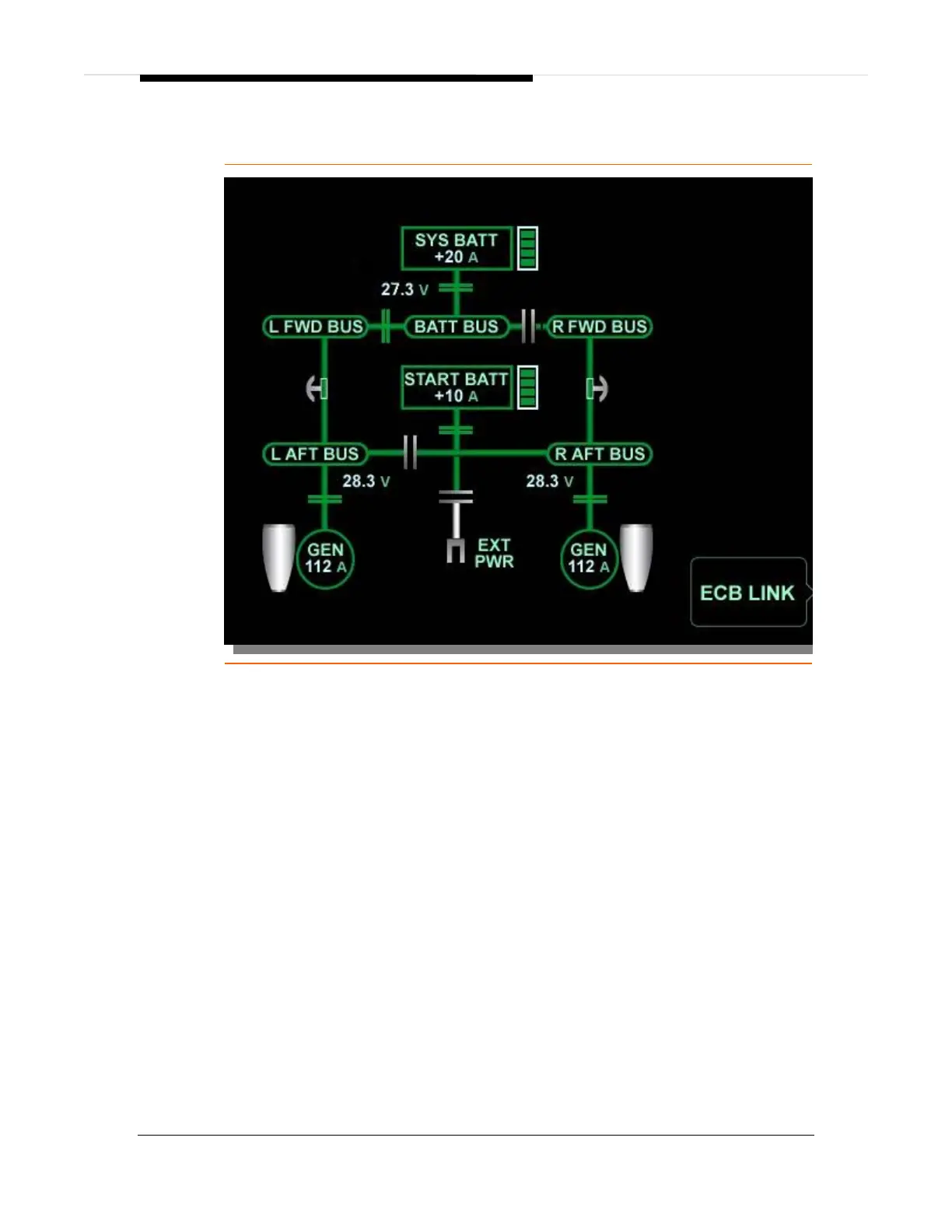
Figure 140. Electrical Synoptic
The electrical synoptic displays the following:
Position of all electrical contactors
Battery charge or discharge
Current flow
Voltage on certain buses
Generator current output
GENERATOR OUTLINE
Green....................................................................................... Generator operating
White................................................................................................... Generator off
Amber ..........................................................................Generator failed/inoperative
BATTERY OUTLINE
Green............................................................................................ Battery Charging
Amber ....................................................................................... Battery Discharging
White................................................Battery Contactor Open (no power to or from)
Bus bar segments are green if voltage is greater than 20 volts.
Bus bar segments are white if voltage is 20 volts or less.
Vertical ribbon to right of batteries indicates state of battery charge in volts.