Modbus Read, Write and Override Parameters plus Exception Codes
106 UDC2500 Universal Digital Limit ControllerProduct Manual 8/05
10.4.6 Alarms
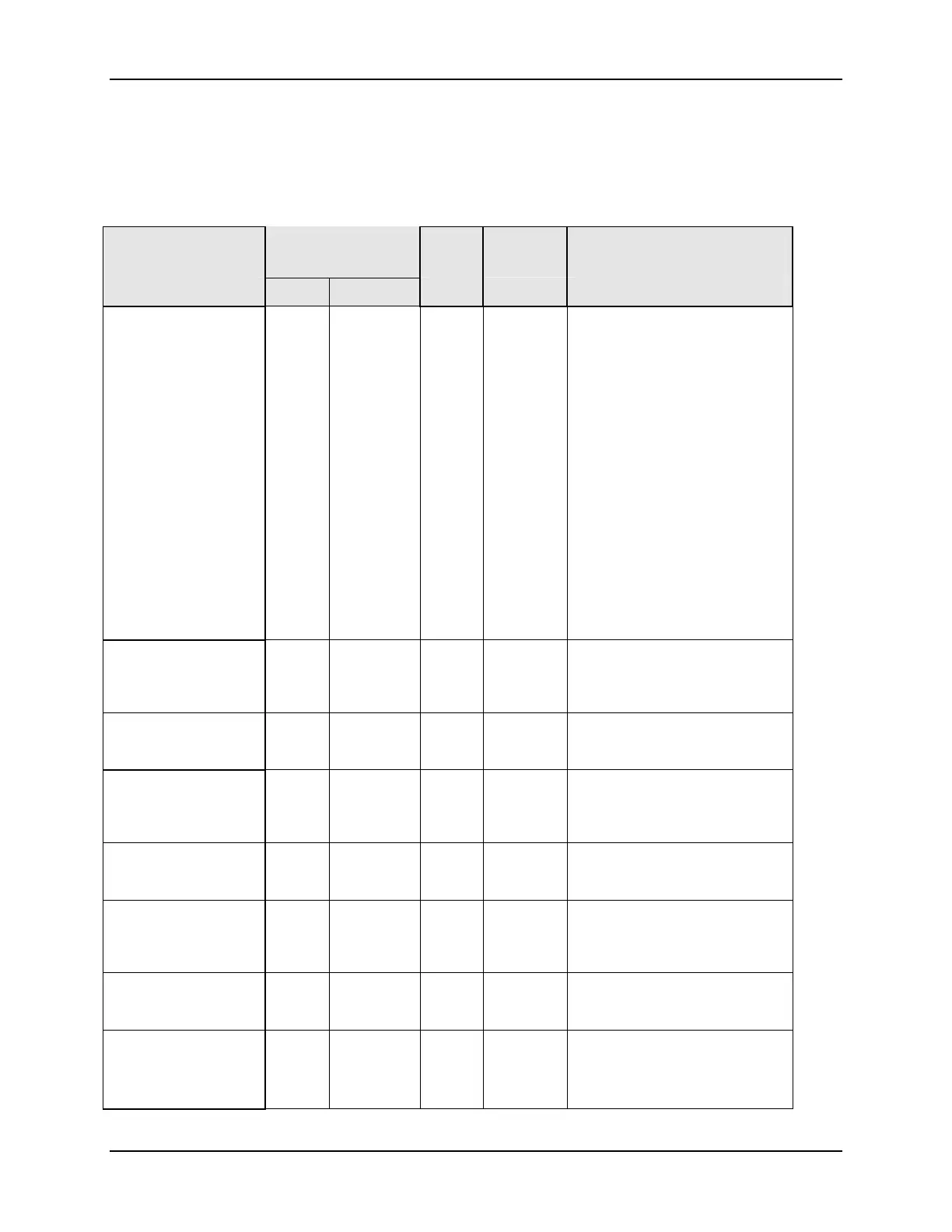
Table 10-8 lists all the register addresses and ranges or selections for the function
parameters in Set-up Group Alarms.
Table 10-8 Set-up Group – Alarms
Parameter
Description
Register
Address
Data
Type
Access Data Range or
Enumerated Selection
Hex Decimal
Alarm 1 Setpoint 1
Type
008C 140 INT R/W
0 = None
1 = Not Used
2 = Not Used
3 = PV
4 = Deviation
5 = Not Used
6 = Alarm on Shed
7 = Not Used
8 = Not Used
9 = Not Used
10 = T/C Warning
11 = Failsafe or T/C Fail
12 = PV Rate of Change
13 = Alarm on Digital
Input
Alarm 1 Setpoint 1
Value
0009 009 FP R/W Within the range of
selected parameter or PV
span for deviation alarm
Alarm 1 Setpoint 2
Type
008E 142 INT R/W Same as 140
Alarm 1 Setpoint 2
Value
000A 010 FP R/W Within the range of
selected parameter or PV
span for deviation alarm
Alarm 2 Setpoint 1
Type
0090 144 INT R/W Same as 140
Alarm 2 Setpoint 1
Value
000B 011 FP R/W Within the range of
selected parameter or PV
span for deviation alarm
Alarm 2 Setpoint 2
Type
0092 146 INT R/W Same as 140
Alarm 2 Setpoint 2
Value
000C 012 FP R/W Within the range of
selected parameter or PV
span for deviation alarm