Installation
18 UDC2500 Universal Digital Limit ControllerProduct Manual 8/05
2.7 Wiring Diagrams
Identify Your Wiring Requirements
To determine the appropriate diagrams for wiring your controller, refer to the model
number interpretation in this section. The model number of the controller can be found on
the outside of the case.
Wiring the Controller
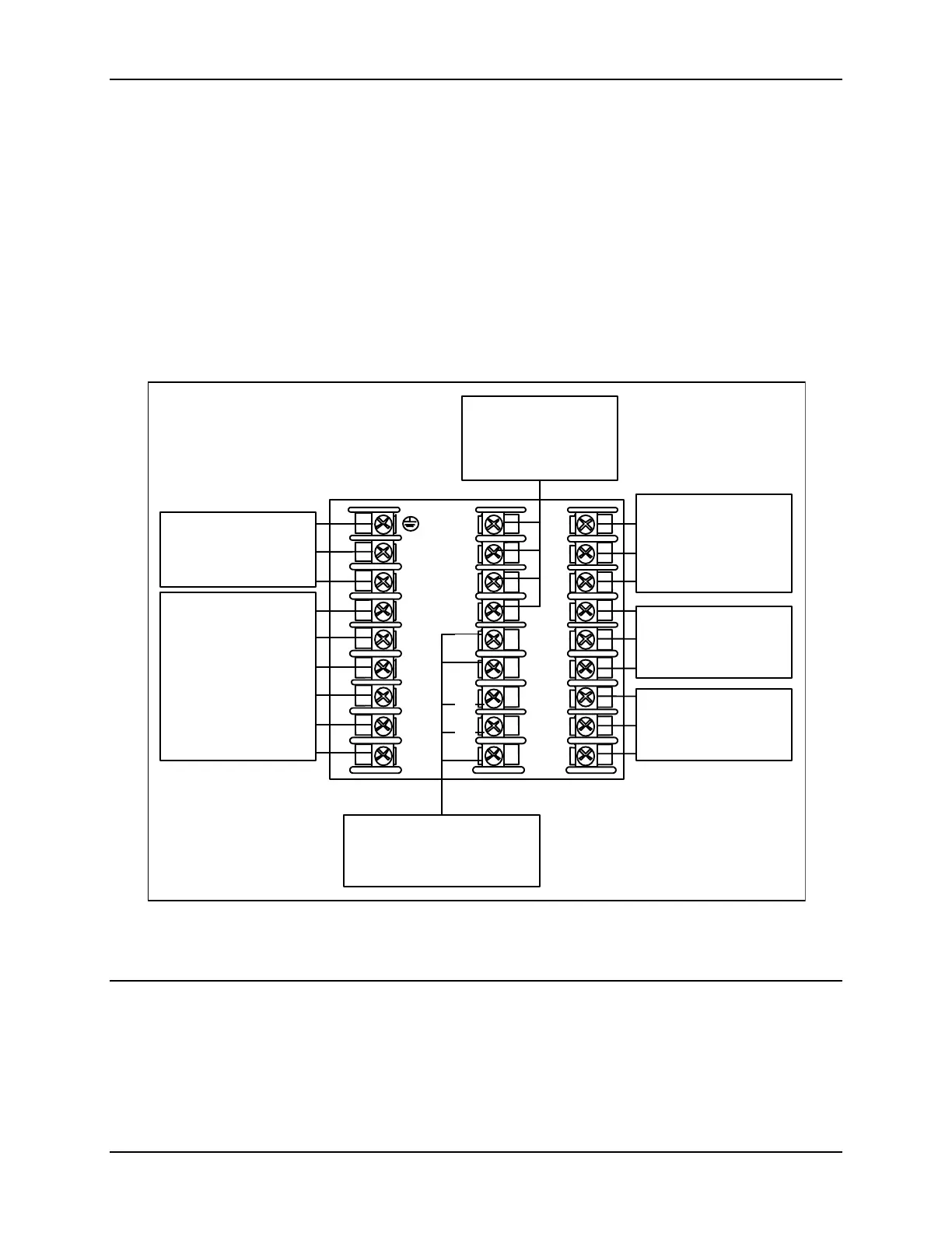
Using the information contained in the model number, select the appropriate wiring
diagrams from the composite wiring diagram below. Refer to the individual diagrams
listed to wire the controller according to your requirements.
L1
L2/N
4
5
6
uxiliary Output
and Digital Inputs
Terminals
See Figure 2-17
AC Line Voltage
Terminals
See Figure 2-5
Not
Used
10
11
12
13
14
15
16
17
xxxx
7
8
9
Limit Relay
Terminals
See Figures 2-8
through 2-14
Input #1
Terminals
See Figure 2-6
20
21
22
23
24
25
26
27
Outputs 3 and 4
Terminals
See Figures 2-8
through 2-14
18
Communications
Terminals
See Figures 2-15 and 2-16
19
Figure 2-4 Composite Wiring Diagram