Installation
8/05 UDC2500 Universal Digital Limit ControllerProduct Manual 23
1
Do not run the communications lines in the same conduit as AC
power. Correct connections may require the use of an Ethernet
cross-over cable.
COMMUNICATION MASTER
OR SWITCH
RXD+SHLD
16 RXD-
17 TXD+
18 TXD-
14 SHLD
15 RXD+
RXD-
TXD+ TXD-
1
2
Use Shielded twisted-pair, Category 5 (STP CAT5) Ethernet cable.
2
3
Use Switch rather than Hub to maximize performance.
3
1
Do not run the communications lines in the same conduit as AC
power. Correct connections may require the use of an Ethernet
cross-over cable.
COMMUNICATION MASTER
OR SWITCH
TXD–SHLD
16 RXD
–
17 TXD +
18 TXD
–
14 SHLD
15 RXD +
TXD+
RXD–
RXD
+
1
2
Use Shielded twisted-pair, Category 5 (STP CAT5) Ethernet cable.
2
3
Use Switch rather than Hub to maximize performance.
3
3
1
Do not run the communications lines in the same conduit as AC
power. Correct connections may require the use of an Ethernet
cross-over cable.
COMMUNICATION MASTER
OR SWITCH
RXD+SHLD
16 RXD-
17 TXD+
18 TXD-
14 SHLD
15 RXD+
RXD-
TXD+ TXD-
1
2
Use Shielded twisted-pair, Category 5 (STP CAT5) Ethernet cable.
2
3
Use Switch rather than Hub to maximize performance.
3
3
1
Do not run the communications lines in the same conduit as AC
power. Correct connections may require the use of an Ethernet
cross-over cable.
COMMUNICATION MASTER
OR SWITCH
TXD–SHLD
16 RXD
–
17 TXD +
18 TXD
–
14 SHLD
15 RXD +
TXD+
RXD–
RXD
+
1
2
Use Shielded twisted-pair, Category 5 (STP CAT5) Ethernet cable.
2
3
Use Switch rather than Hub to maximize performance.
3
333
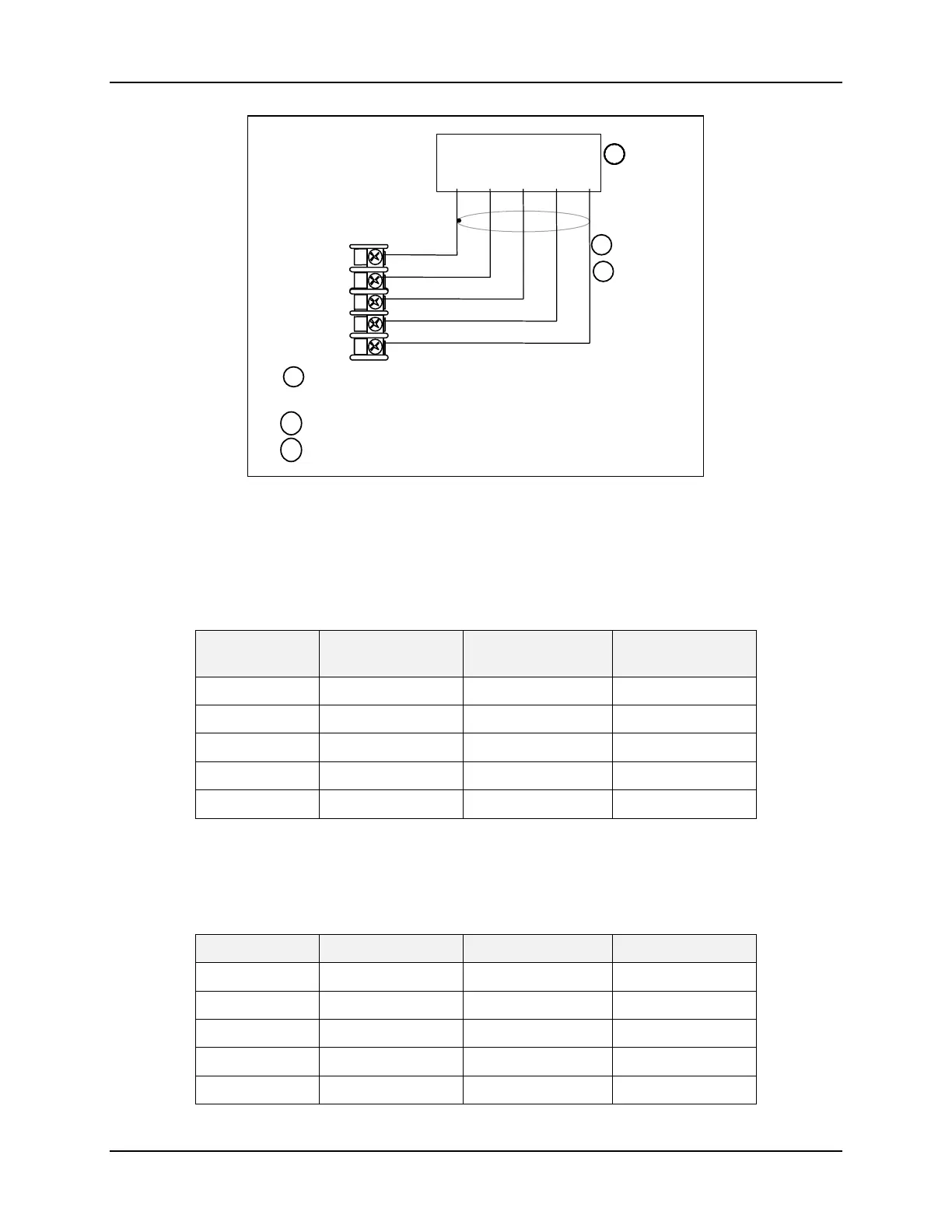
Figure 2-11 Ethernet Communications Option Connections
Figure 2-11 and Table 2-6 shows how to connect a UDC to a MDI Compliant Hub or
Switch utilizing a
straight-through cable or for connecting a UDC to a PC utilizing a
crossover cable.
Table 2-6 Terminals for connecting a UDC to a MDI Compliant Hub or Switch
UDC Terminal UDC Signal Name RJ45 Socket Pin # Switch Signal
Name
Position 14 Shield Shield Shield
Position 15 RXD- 6 TXD-
Position 16 RXD+ 3 TXD+
Position 17 TXD- 2 RXD-
Position 18 TXD+ 1 RXD+
Table 2-7 shows how to connect a UDC directly to a PC utilizing a straight-through cable
(wiring the UDC cable this way makes the necessary cross-over connections)
Table 2-7 Terminals for connecting a UDC directly to a PC utilizing a straight-
through cable
UDC Terminal UDC Signal Name RJ45 Socket Pin # PC Signal Name
Position 14 Shield Shield Shield
Position 15 RXD- 2 TXD-
Position 16 RXD+ 1 TXD+
Position 17 TXD- 6 RXD-
Position 18 TXD+ 3 RXD+