Input Calibration
58 UDC2500 Universal Digital Limit ControllerProduct Manual 8/05
5.3 Preliminary Information
Disconnect the Field Wiring
Tag and disconnect any field wiring connected to the input terminals on the rear of the
controller.
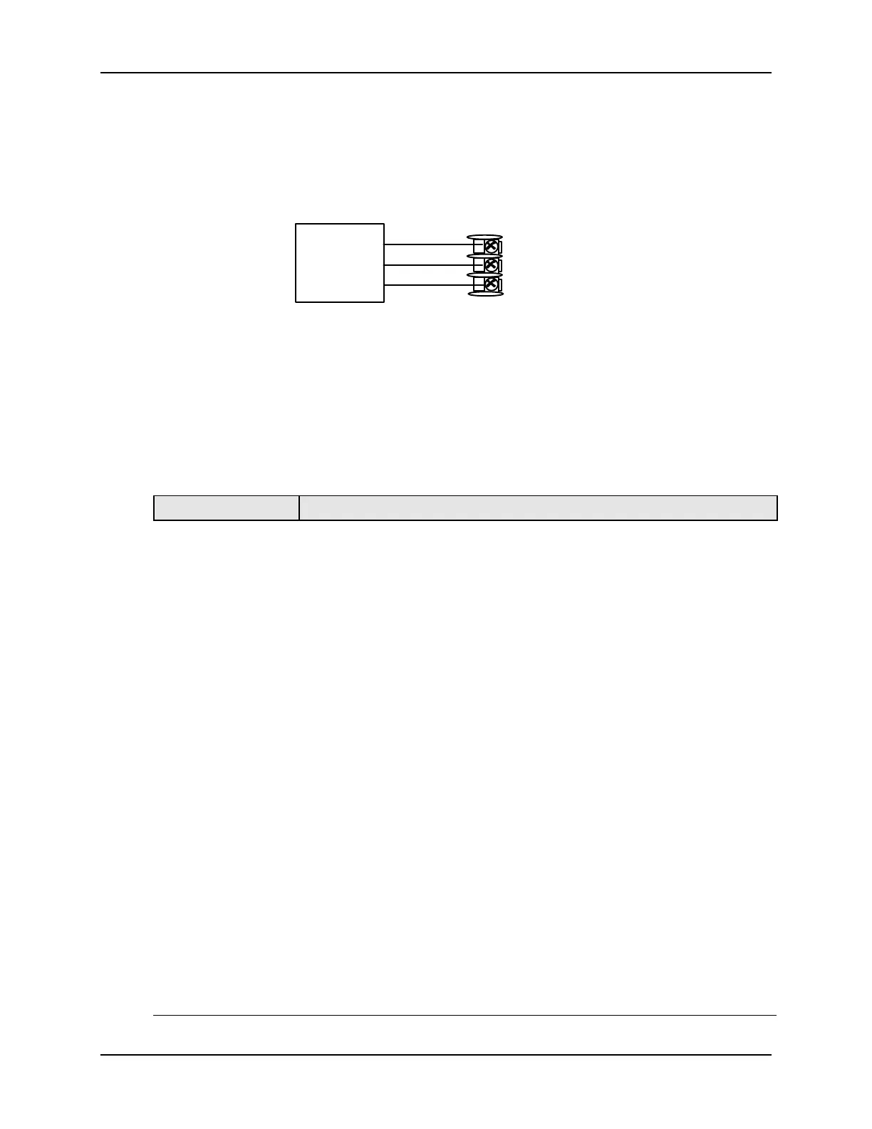
R
+
Input 1
Connections
25 R
26 +
27 –
Input 1
Figure 5-1 Input 1 Wiring Terminals
Equipment Needed
Table 5-2 lists the equipment you will need to calibrate the specific types of inputs that
are listed in the table. You will need a screwdriver to connect these devices to your
controller.
Table 5-2 Equipment Needed
Type of Input Equipment Needed
Thermocouple
Inputs (Ice Bath)
• A calibrating device with at least ± 0.02 % accuracy for use as a
signal source such as a millivolt source.
• Thermocouple extension wire that corresponds with the type of
thermocouple that will be used with the controller input.
• Two insulated copper leads for connecting the thermocouple
extension wire from the ice baths to the mV source.
• Two containers of crushed ice.
Thermocouple
Inputs (T/C Source)
• A calibrating device with at least ± 0.02 % accuracy for use as a
signal source such as a millivolt source.
• Thermocouple extension wire that corresponds with the type of
thermocouple that will be used with controller input.
RTD (Resistance
Thermometer
Device)
• A decade box, with at least ± 0.02 % accuracy, capable of providing
stepped resistance values over a minimum range of 0 to 1400 ohms
with a resolution of 0.1 ohm.
• Three insulated copper leads of equal length for connecting the
decade box to the controller.
Milliampere,
Millivolt, Volts, and
Radiamatic
• A calibrating device with at least ± 0.02 % accuracy for use as a
signal source.
• Two insulated copper leads for connecting the calibrator to the
controller.
• Place current source at zero before switching ON.
• Do not switch current sources OFF/ON while connected to the
UDC2500 input.