Operating the Limit Controller
54 UDC2500 Universal Digital Limit ControllerProduct Manual 8/05
4.7 Alarm Setpoints
Introduction
An alarm consists of a relay contact and an operator interface indication. The alarm relay
is de-energized if setpoint 1 or setpoint 2 is exceeded.
The alarm relay is energized when the monitored value goes into the allowed region by
more than the hysteresis.
The relay contacts can be wired for normally open (NO) energized or normally closed
(NC) de-energized using internal jumper placement. See Table 2-3 in the
Section 2 –
Installation for alarm relay contact information.
There are four alarm setpoints, two for each alarm. The type and state (High or Low) is
selected during configuration. See
Subsection 3– Configuration for details.
Alarm Setpoints Display
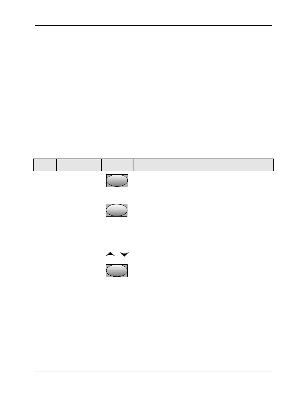
Table 4-5 Procedure for Displaying Alarm Setpoints
Step Operation Press Result
1
Select Alarm
Set-up Group
SetupSetup
Until you see:
Upper Display = SET
Lower Display = ALARMS
2
Access the Alarm
Setpoint Values
FunctionFunctionFunction
To successively display the alarm setpoints and their values.
Their order of appearance is shown below.
Upper Display = (the alarm setpoint value)
Range values are within the range of the selected
parameters:
DE (Deviation) value = within Input 1 Span
PV (Process variable) value = Within Input 1 range
3
Change a value
or
To change any alarm setpoint value in the upper display
4
Return to Normal
Display
Lower
Display
Lower
Display
Lower
Display