Output Calibration
8/05 UDC2500 Universal Digital Limit ControllerProduct Manual 69
Procedure
The procedure for calibrating the auxiliary output is listed in Table 6-2. The numeric
codes are also listed.
Make sure “LOCK” in the Lock Set Up group is set to “NONE” (see
Subsection 3.4).
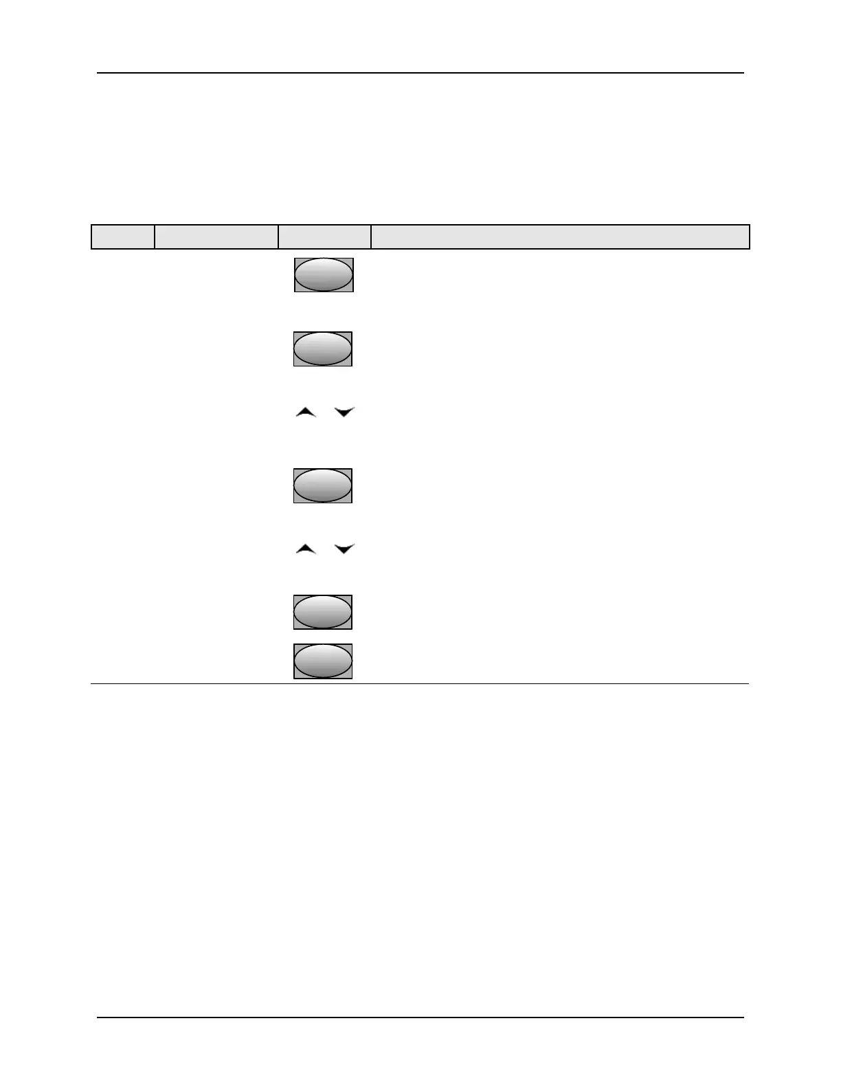
Table 6-2 Auxiliary Output Calibration Procedure
Step Operation Press Result
1
Enter Calibration
Mode
SetupSetup
until you see
Upper Display = CAL
Lower Display = AUXOUT
2
Calibrate 0 %
FunctionFunctionFunction
You will see:
Upper Display = A Value
Lower Display = ZROVAL
or
until the desired 0 % output is read on the milliammeter,
use the values shown below depending on the action of
your controller.
3
Calibrate 100 %
FunctionFunctionFunction
To store the 0 % value you will see:
Upper Display = A Value
Lower Display = SPNVAL
or
until the desired 100 % output is read on the milliammeter.
4
FunctionFunctionFunction
The controller stores the span value.
Exit the
Calibration Mode
Lower
Display
Lower
Display
Lower
Display
To exit the calibration mode.
6.3 Restore Output Factory Calibration
Introduction
The factory calibration constants for the Auxiliary Outputs are stored in its non-volatile
memory. Thus, you can quickly restore the “Factory Calibration” for those outputs by
simply changing the ARANGE to the other setting and then changing it back to the
original type.
Refer to Table 6-3 Restore Factory Calibration for procedure