Output Calibration
68 UDC2500 Universal Digital Limit ControllerProduct Manual 8/05
Table 6-1 Set Up Wiring Procedure for Auxiliary Output
Step Action
1
Apply power and allow the controller to warm up 30 minutes before you calibrate.
2 Set LOCK in the Tuning Set Up group to NONE.
3
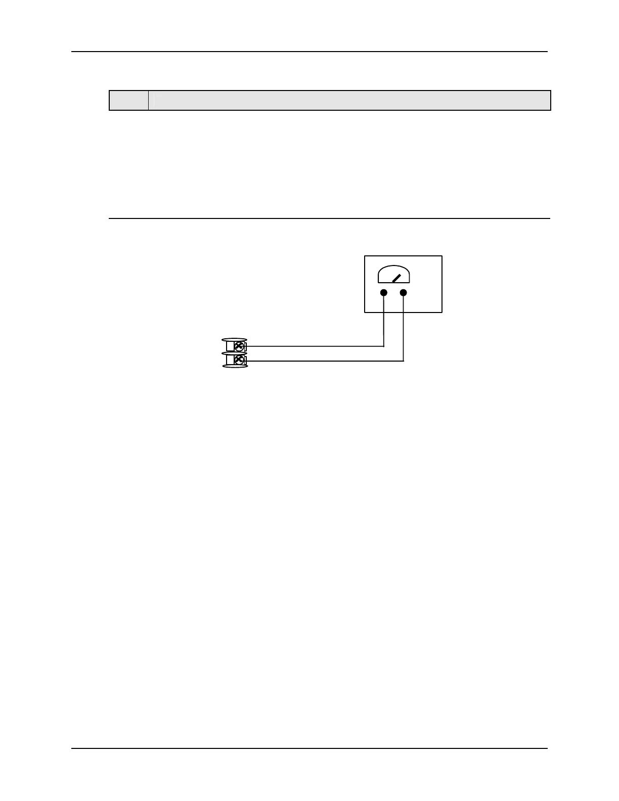
Tag and disconnect the field wiring, at the rear of the controller, from terminals 12 (+)
and 13 (–). See Figure 6-1.
4
Connect a milliammeter across these terminals.
xxxx
12
13
Milliammeter
+
+
Figure 6-1 Wiring Connections for Calibrating Auxiliary Output