1 Product Description
ED-HMI2120-101C User Manual 1-13
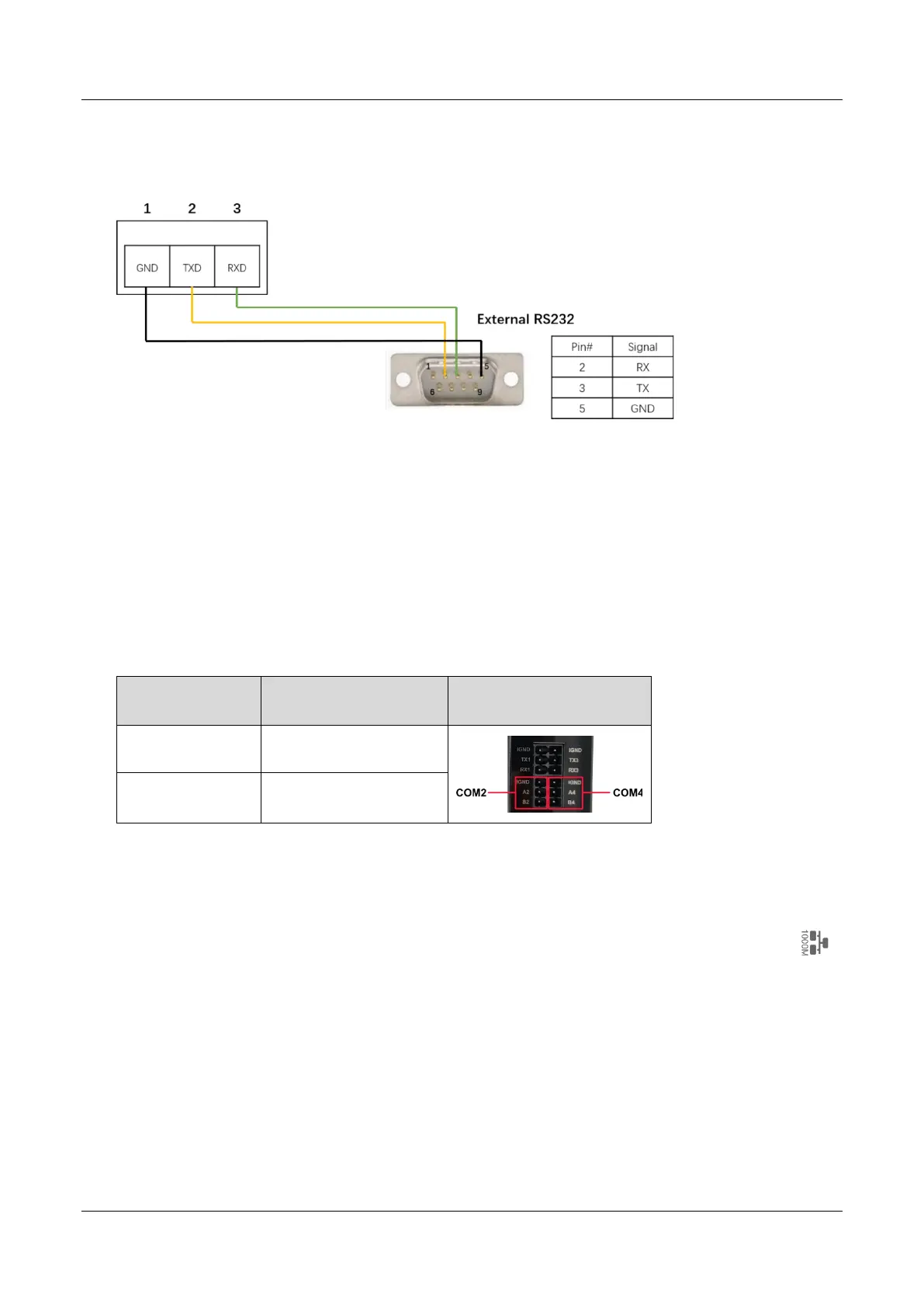
Schematic diagram of RS232 wires is as follows:
RS485 Terminal Resistor
ED-HMI2120-101C includes 2 RS485 ports, and a 120Ω terminal resistor is configured at the end of
each RS485 bus to ensure the transmission of high-frequency signals, and the terminal resistor has
been connected through a jumper cap by default.
The position of the 120Ω terminal resistor of the 2 RS485 in the PCBA and the relationship between
the RS485 ports and corresponding COM ports are shown in the table below.
Location in PCBA Corresponding COM port
The specific location of
the corresponding COM
J22 COM2
J24 COM4
1.6.5 1000M Ethernet Interface
ED-HMI2120-101C includes one adaptive 10/100/1000M Ethernet port, and the silkscreen is " ".
The connector model is Trxcom TRJG0926HENL, which can support PoE through the expansion
module. When accessing to network, it is recommended to use the network cable of Cat6 and above.
The pins corresponding to the terminal are defined as follows: