HELM PUMP MODEL
WHEEL TURNS WHEEL TURNS
& DISPLACEMENT HC5370 HC5380
1.7 cu.in. per revolution 4.8/5.7 5.5/6.5
2.0 cu.in. per revolution 4.0/4.8 4.6/5.5
2.4 cu.in. per revolution 3.5/4.0 3.9/4.6
Power Assist for SeaStar Systems
9
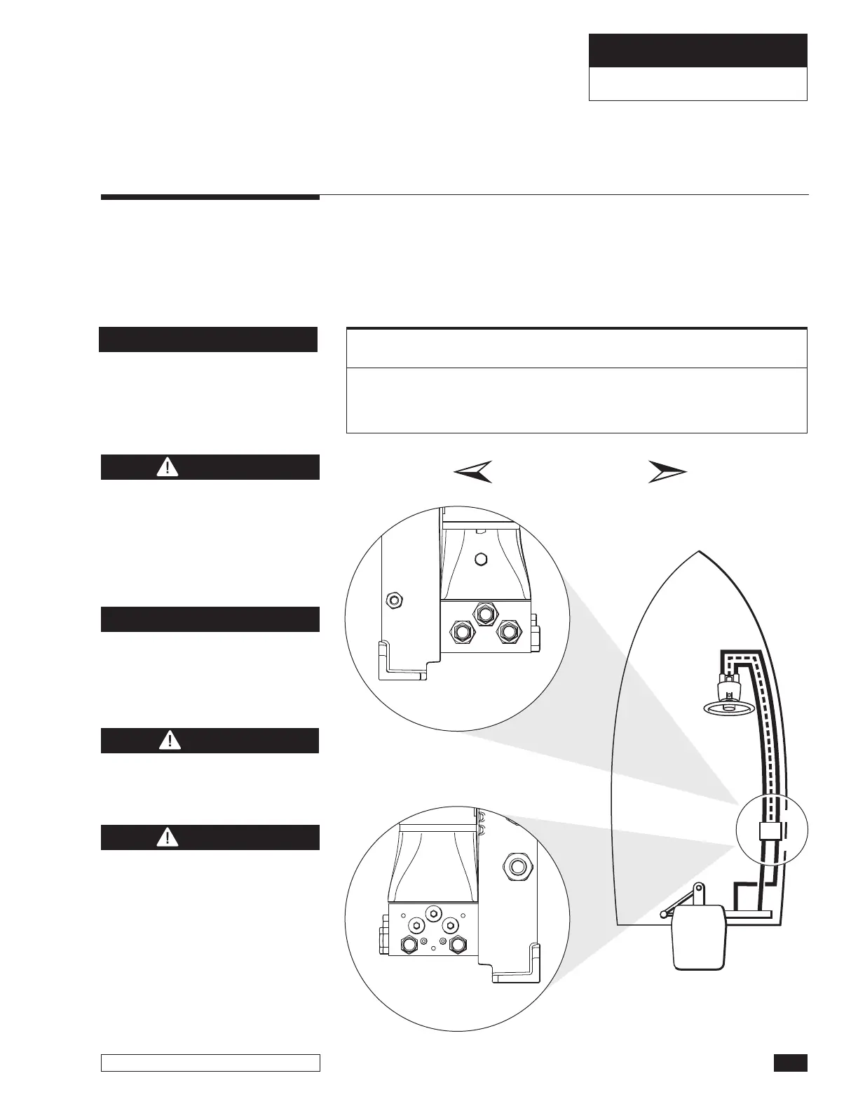
Hose connection is as follows.
•
Helm to P/A = S (helm) to H1 (P/A), P (helm) to H2 (P/A), lower R
port (helm) to R (P/A).
•
P/A to cylinder = C1 (P/A) to starboard side (cylinder). C2 (P/A) to
port side (cylinder).
SeaStar Outboard Side Mount and
Splashwell Mount Cylinders
Side Mount Cylinder:
HC5370
Splashwell Cylinder:
HC5380
SYSTEM INSTALLATION
SEASTAR POWER ASSIST
DO NOT use SeaStar PRO systems
with HC5370 side mount and/or
HC5380 Splashwell mount
cylinders as SeaStar PRO systems
are not compatible with any
unbalanced cylinder.
WARNING
Hoses MUST be at least 6' in
length from the power assist to
the helm pump, or, from the
power assist to the cylinder(s).
NOTICE
Figure 6.
Unbalanced cylinder will result
in unequal wheel turns.
NOTICE
CAUTION
ALL hose connections MUST be
torqued to 15 ft-lb (20.34Nm).
DO NOT run the wires or hoses
in areas where the may come
in contact with battery acid or
excessive heat, i.e. engine
exhaust, manifolds or any
other area that may damage
the wires or hoses.
WARNING



 To Next Page