STP-iX455/iXL455 Series Instruction Manual
13-2
Troubleshooting
13.2 Troubleshooting
13.2.1 Indication of "FAILURE" LED
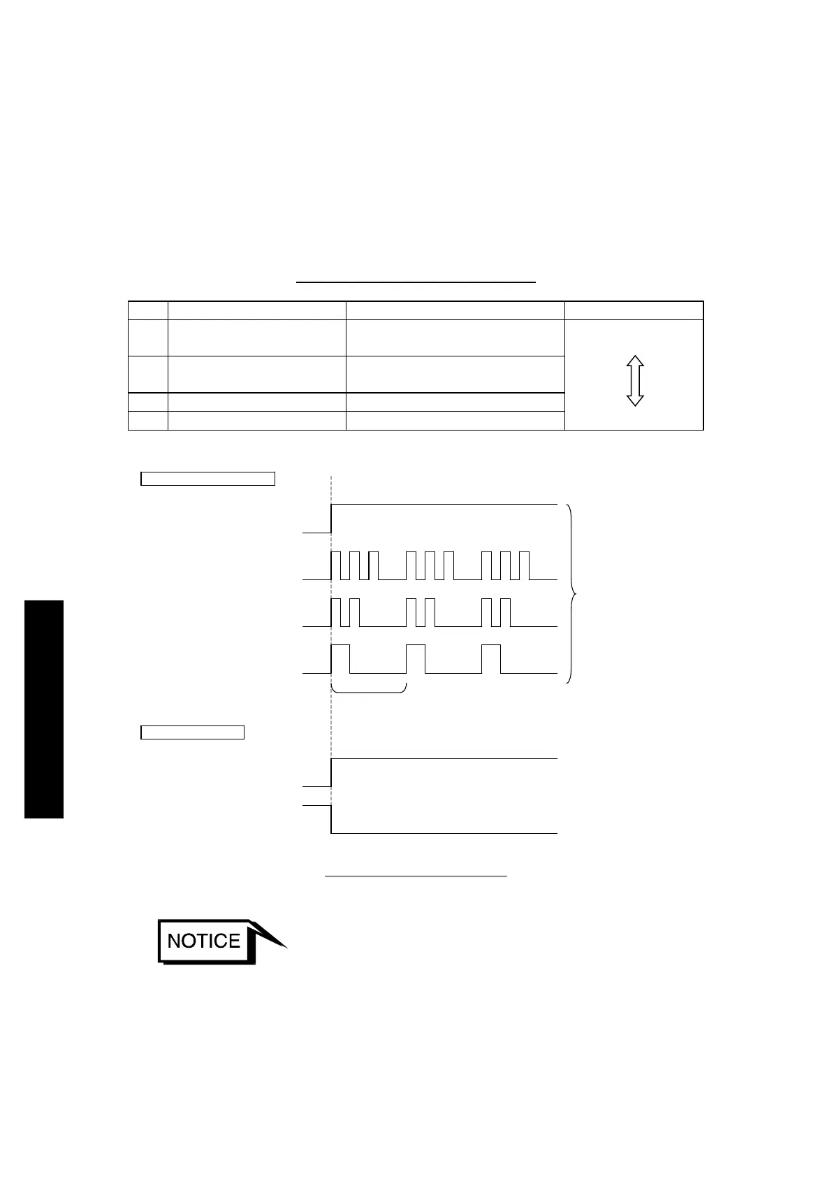
The flashing pattern of the "FAILURE" LED (red) differs depending on the type of
abnormality/error. When two or more failures are detected simultaneously, a
high-priority failure is indicated. Also, the failure signal is output from the "X2
REMOTE" connector.
If an abnormality/error is found, take measures in accordance with Table 13.2.
Table 13.1 Priority of Failure Signal
1
Overspeed, and other
Steady red
High
2
CNT Overheat
3 flashes in red
1 cycle
Disturbance
(
1 flash in red
)
OFF
↓
Failure detection
"FAILURE" LED indication
X2 REMOTE output
ON
DRV Overload
(
2 flashes in red
)
MOTOR Overheat
CNT Ove
(
3 flashes in red
)
Corresponding to
failure type
OFF
OFF
ON
ON
ON
OFF
FAILURE N.O OUT
(8)–(21)
OFF
ON
Power Failure
Overspeed
(
steady in red
)
ON
OFF
FAILURE N.C OUT
(9)–(21)
Figure 13.1 Failure Output
◇ The STP-Link (optional accessory) and the display unit (optional accessory)
display an error as a message. Also, the errors being detected can be read via
serial communication.
 Loading...


