Connecting
6.9 Serial interface
SCD 19102 / SMD 19102
34 Instruction Manual, 10/2011, A5E01588521A-004
6.9 Serial interface
WARNING
• Apart from the serial spot meter and the universal serial luminance meter, no other
devices are permitted to be connected to the service socket.
• Connection and removal of a unit may only be carried out by servicing personnel or
those trained by them.
• Serial Spot Meters or Serial Luminance Meters must not be connected in the presence
of patients.
The display has three serial RS 232 interfaces:
● Downstream RJ11 socket:
identified in the Fig. "Possible configuration – serial bus mode" by "2". The socket is
located on the right (landscape version) or at the bottom (portrait version) on the rear of
the display.
● Upstream RJ11 socket:
identified in the Fig. "Possible configuration – serial bus mode" by "1". The socket is
located on the left (landscape version) or at the top (portrait version) on the rear of the
display, right next to the VGA plug.
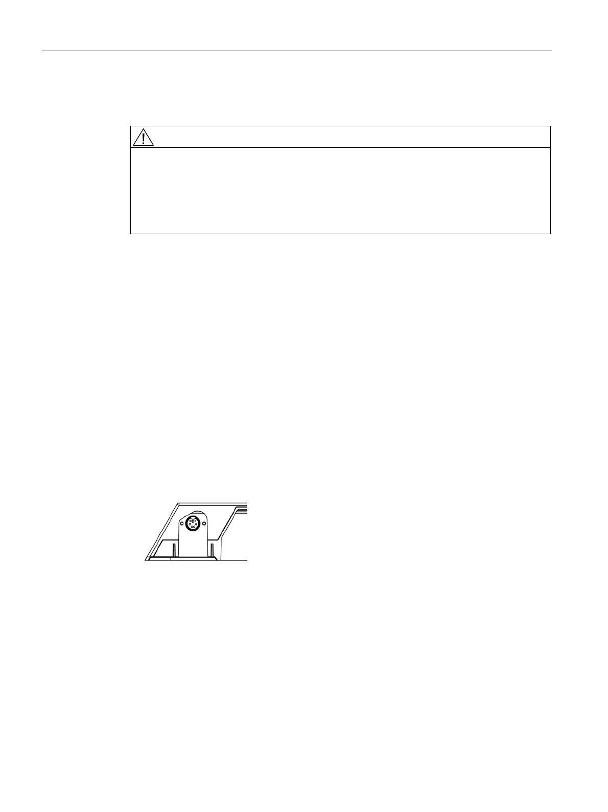
● 6-pin mini-DIN socket (downstream):
identified in the drawing below as “3”.
This serial interface (also called the "service socket") is easily accessible at the rear of
the display. The 6-pin mini-DIN socket is available for the connection of a Universal Serial
Luminance Meter or a Serial Spot Meter.
Please note the diagram for the "6-pin mini-DIN socket": It shows the lower left corner of
the underside of the display (viewed from rear).
Figure 6-5 Service socket for measuring instruments