EasyManua.ls Logo

eldoLED LINEARdrive - 3.3.1 Locating the right connector; 3.3.1.1 Connecting power leads

eldoLED LINEARdrive
46 pages
Print Icon
To Next Page IconTo Next Page
To Previous Page IconTo Previous Page
Loading...
21
3.3.1 Locating the right connector
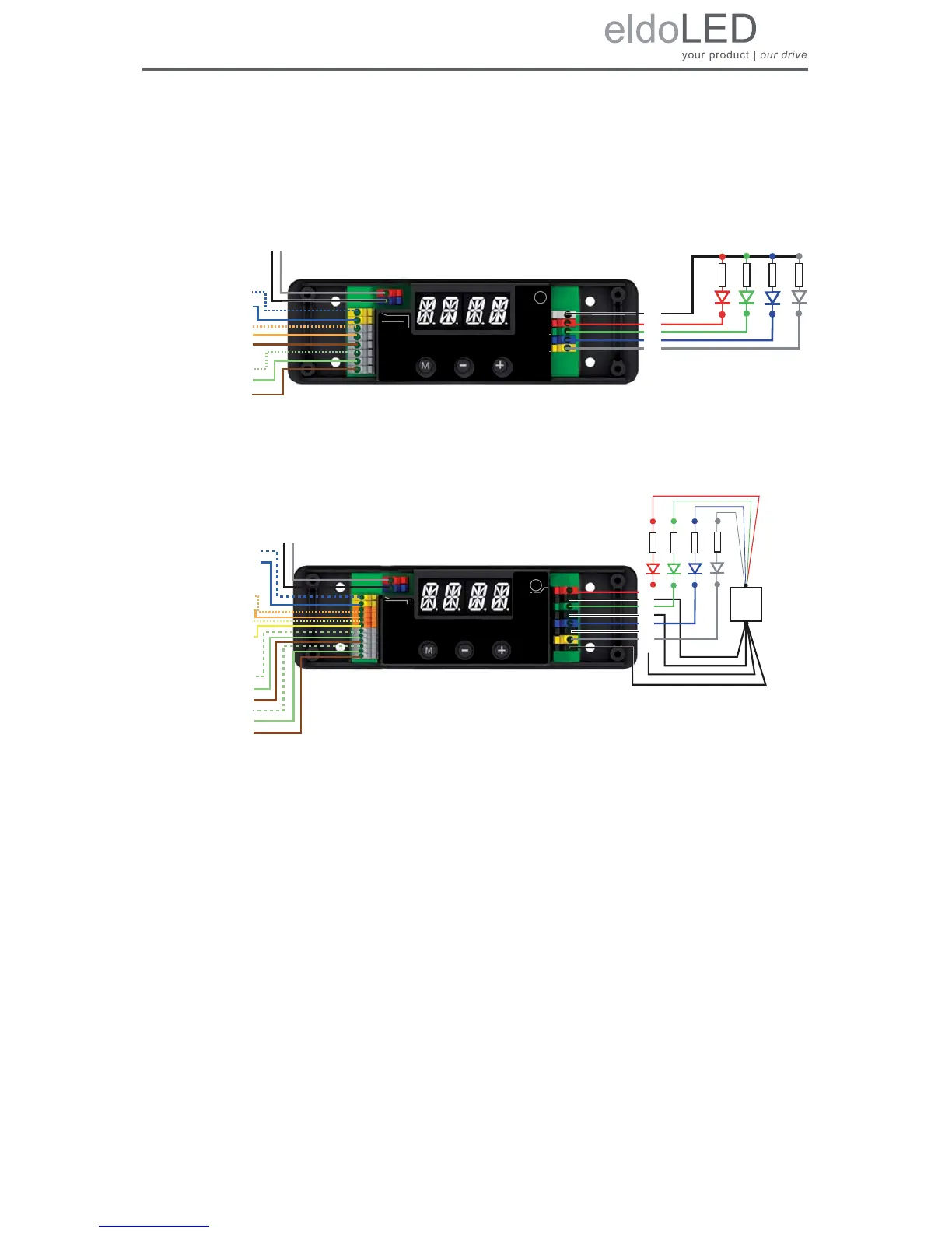
The figures below show the wiring diagrams for the LINEARdrive Display 180 and 720 and are
followed by a short explanation of the LINEARdrive’s springcage connectors.
Figure 3.3: LINEARdrive Display 180 wiring diagram
Figure 3.4: LINEARdrive Display 720 wiring diagram
3.3.1.1 Connecting power leads
Connect the positive voltage supply wire of the 12V-28V DC power supply to the VDC+ con-
nector, and the negative voltage supply wire to the VDC- connector.
The power leads should have an insulating capacity of 100 volts or more, and the leads’ insu-
lation must be able to withstand temperatures of 85
°C or more.
Ext in +
Ext in
DMX in +
DMX in -
DMX in shield
LedSync thru +
LedSync thru -
LedSync shield
TC
1
2
3
Group
Group
Group
Group
LED supply +
LINEARdrive 180D
-
4
12-28V / 6A Direct voltage controlled LED driver
LED groups
DMX in shield
DMX in +
DMX in -
Ext in +
Ext in -
{
12V-28V DC IN
VDC -
VDC +
LedSync thru shield
LedSync thru +
LedSync thru -
R
R
W
R
B
G
LED sup
R
R
DMX in -
DMX in +
LedSync shield
DMX in Shield
EXT in +
EXT in -
DALI in +
DALI in -
DALI out +
DALI out -
{
12V-28V DC IN
VDC -
VDC +
R
R
-
R
W
G
B
+
R
R
LGND
LedSync out -
LedSync out +
TC
Group 1
LINEARdrive 720D
Group 1 GND
Group 2 -
Group 2 GND
Group 3 -
Group 4 GND
Group 4 -
Group 3 GND
Ext in +
Ext in
DMX in +
DMX in -
DMX in shield
LedSync out +
LedSync out -
LedSync shield
-
DALI out -
DALI out +
DALI in -
DALI in +
12-28V / 24A Direct voltage controlled LED driver

Table of Contents

Related product manuals