Basic Information
1-3
Contrast ........................................................................ 3-16
Brightness .................................................................... 3-17
Volume ......................................................................... 3-17
Language ..................................................................... 3-17
Cycle Description ......................................................... 3-17
Status Display .............................................................. 3-17
Install Cycle (WaveTouch™) ............................................. 3-18
Install Cycle (IQ Touch™) ................................................. 3-18
Diagnostics and Error Codes ............................................ 3-19
Reading Error Codes ......................................................... 3-19
To Clear Latest Stored Error Code ................................... 3-19
Diagnostic Test .................................................................. 3-20
To Start the Diagnostic Test ........................................ 3-20
Exiting Diagnostic Mode .............................................. 3-20
Error Code Chart ............................................................... 3-21
Error Code Test Chart ....................................................... 3-22
Section 4- Component Teardown .................................. 4-1
Warnings and Cautions ..................................................... 4-1
Door Components ............................................................. 4-2
Door Trim Ring .......................................................... 4-2
Door Assembly ............................................................ 4-2
Striker Plate ................................................................ 4-3
Inner Door Glass .......................................................... 4-3
Latch Indicator ............................................................. 4-3
Outer Door Glass ......................................................... 4-4
Door Hinge .................................................................. 4-4
Door Lock Assembly .................................................... 4-5
Bellows .............................................................................. 4-5
Reinstalling or Replacing the Bellows ............................... 4-6
Interior Light ...................................................................... 4-7
Top Panel .......................................................................... 4-7
Vibration Dampener .......................................................... 4-7
Detergent Drawer Removal and Breakdown ..................... 4-8
Console Panel ................................................................... 4-8
Control Assembly Removal and Breakdown ..................... 4-9
Front Panel ........................................................................ 4-10
Controller Assembly .......................................................... 4-10
Weight Ring ....................................................................... 4-11
Water Inlet / Overflow Vent Tube Grommet ...................... 4-11
Overflow /Vent Tube .......................................................... 4-12
Water Inlet Valve Assembly .............................................. 4-12
Water Inlet Screen ............................................................. 4-13
Top Rear Brace ................................................................. 4-13
External Drain Hose .......................................................... 4-13
Detergent Cavity Assembly ............................................... 4-14
Detergent Dispenser Outlet Hose ..................................... 4-14
Power Cord ....................................................................... 4-15
Rear Access Cover ........................................................... 4-15
Suspension Spring ............................................................ 4-15
Top Center Brace .............................................................. 4-16
Electric Water Level Sensor .............................................. 4-16
Drain Pump ....................................................................... 4-16
Drive Belt ........................................................................... 4-17
Large Pulley ...................................................................... 4-17
Drive Motor ........................................................................ 4-17
Speed Control Board Assembly ........................................ 4-18
Air Bell ............................................................................... 4-18
Heating Element ................................................................ 4-19
Air Shock Absorber ........................................................... 4-19
Tub Assembly .................................................................... 4-20
Section 5- Troubleshooting .............................................. 5-1
Troubleshooting Chart ......................................................... 5-1
Component Resistance Chart ............................................. 5-5
Section 6- Wiring Diagrams ............................................. 6-1
Wiring Diagram Models
EWFLW65H & EIFLW55H .................................................. 6-1
Important Safety Instructions
Safety Precautions
Do not attempt to install, operate or service the unit until
you have read the safety precautions in this manual.
Safety items throughout this manual are labeled with a
Danger, Warning, or Caution based on the risk type.
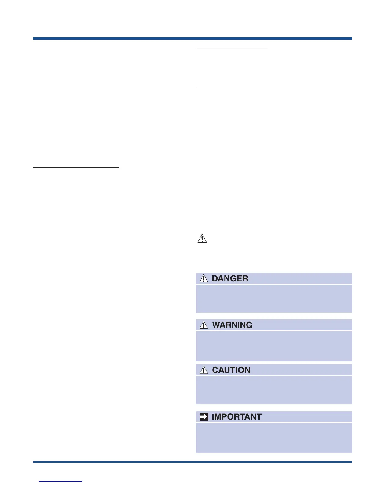
Definitions
This is the safety alert symbol. It is used to alert
you to potential personal injury hazards. Obey all
safety messages that follow this symbol to avoid possible
injury or death.
DANGER indicates an imminently hazardous
situation which, if not avoided, will result in death
or serious injury.
WARNING indicates a potentially hazardous
situation which, if not avoided, could result in
death or serious injury.
CAUTION indicates a potentially hazardous
situation which, if not avoided, may result in minor
or moderate injury.
Indicates installation, operation, or maintenance
information which is important but not hazard
related.