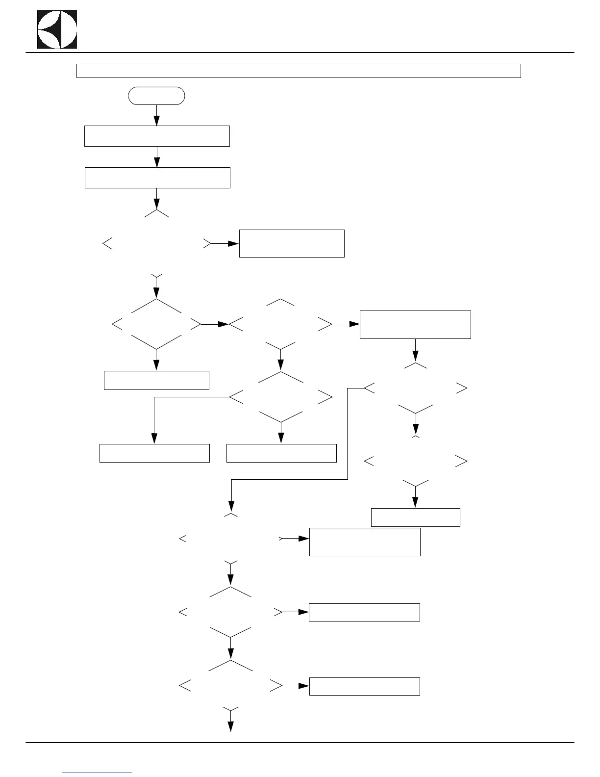
SHORT COMPACT RTCS90/ WTCS90 AND RTCS140/ WTCS140 WITHOUT DT/HAB
NO
Alarm EMR: error message on display.
START
Check the connection of the
emergency buttons on auxiliary
board AP1 (located inside the
electrical box in the wash zone).
See figure Layout 9 - page 72 -
terminal x_IN (contacts 7 and 8)
and X_OUT (contacts 11 and
12).
YES
Interruption in emergency circuit.
Correctly connect and make sure
the insulation is not pinched.
NO
Make sure the emer-
gency buttons have not
been activated.
YES
NO
Check continuity on the
board AP1 between con-
tacts 7-8 of Terminal Block
X-IN and contacts 11-12 of
Terminal Block X-OUT.
YES
Deactivate the emergency buttons.
Check the emergency circuit power
supply voltage.
NO
Make sure the wiring be-
tween board AP1 and
each of the emergency
buttons is not interrupted.
YES
Replace/repair the wiring.
Replace the faulty buttons.
NO
Check the correct 24V output
power supply from trans-
former GS1 (connector J49
contact 1 and connector J50
contact 2).
Check the correct 230V input
power supply to the trans-
former GS1 (connector J44,
contacts 1-3), checking on
the transformer terminal
board.
YES
Replace the transformer.
Check the continuity between
connector J49 (contact 1 on
GS1) and connector J32 (con-
tact 6 on AP1) and between con-
nector J50 (contact 2 on GS1) to
J32 (contact 2 on AP1).
YES
NO
Check the wiring and connectors and
repair/replace if necessary.
Check continuity between con-
nector J32 (contact 3 on AP1)
to terminal X_OUT (contact 9
on AP1).
YES
NO
Replace board AP1.
Check the continuity be-
tween connector J32 (con-
tact 2 on AP1) and
connector J27 (contact 3 on
AP1).
YES
NO
Replace board AP1.
YES