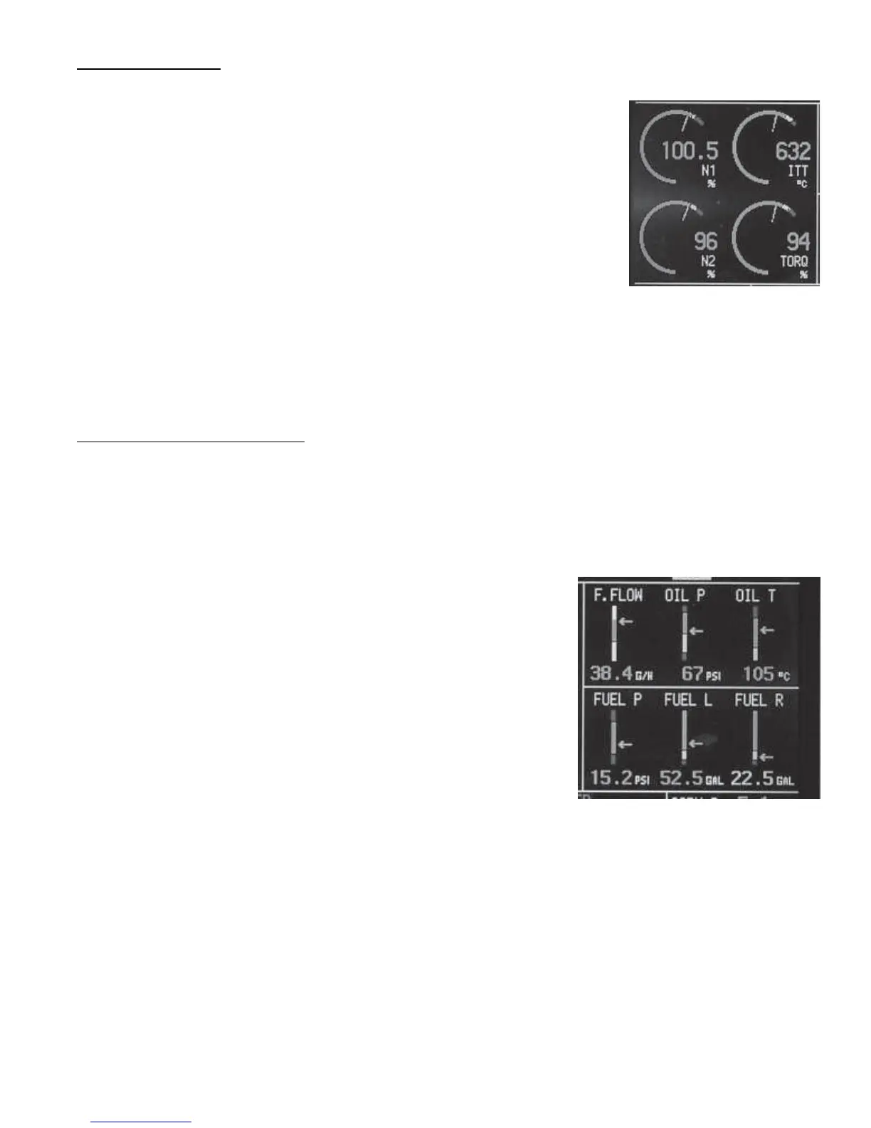
2.3 Arc Gauges:
The Arc Gauges incorporate a digital readout and an analog arc. The color of the
digital readout will reflect the current operating level of the instrument (i.e., if the N1
is operating in the red, the digital readout will be red).
The digital display can be set to blink when a functions operating level reaches a
yellow and/or red operating range. To stop the blinking, push any button, or rotate
the SELECT knob. Also, acknowledging a voice warning using the external
“Voice Alarm Control Panel” will stop the blinking of any digital display. The “4.
Redlines, Limits and Color Setup” screen found in section 6.3.4 of this manual
provides a control to enable or disable the blinking for any function and set its
operating limits.
The location and types of functions displayed in the Arc Gauge area can be set. This can be accomplished in the “2.
2. Function to Main Screen Mapping” screen found in section 6.3.2 of this manual.
2.4 Vertical Strip Gauges:
The Vertical Strip Gauges provide the following features:
A. The colored operating ranges shown on the Vertical Strip are programmable and may be set up for any
aircraft. See section 6.3.4 of this manual to set the operating ranges and various display colors for any
instrument displayed on the MVP screen.
B. Each Vertical Strip Gauge features an arrow indicating its current
operating level. Also, the arrow allows you to interpret rate and
trend information and provides field of vision data.
C. A digital display is featured with each Vertical Strip Gauge.
D. The digital display can be set to blink when a function’s operating
level reaches a yellow and/or red operating range. To stop the
blinking, push any button, or rotate the Select knob. Also,
acknowledging a voice warning using the external “Voice Alarm
Control Panel” will stop the blinking of any digital display. The
“4. Redlines, Limits and Color Setup” screen found in section 6.3.4 of this manual provides a control to
enable or disable the blinking for any function and set its operating limits.
E. The Vertical Strip Gauges may be rearranged or configured to display various functions. See section
6.3.2 of this manual to set which function is to be displayed at a specific display location.
8

 Loading...

