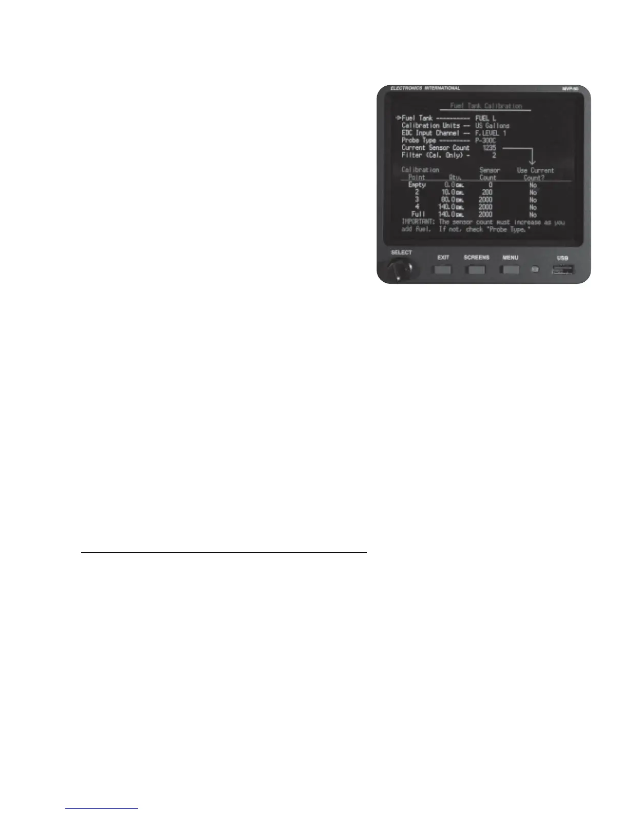
“Fuel Tank”: This field selects the fuel tank to be calibrated. You can switch between tanks any time during
the calibration cycle.
Note: The tanks must be calibrated in US gallons. Fuel
levels may be displayed in other units by changing the
“Display Units” field in the “3. Redlines, Limits and Color
Setup” screen (found in the “*.0 System Configuration
Screens” section of this manual).
“Current Sensor Count”: This is the output count
measured on the fuel level probe. A sensor count represents
a fuel level. The calibration process below associates a
sensor count to a fuel level.
“Calibration Filter”: When fuel is added to the tank the
sensor count will increase. When you stop adding fuel to the
tank the sensor count will continue to climb for a short period
of time and then stop climbing. If the sensor count does not
settle out (continues to jump up and down), increase the “Calibration Filter.” The higher the Calibration Filter
the more stable the counts will be and the longer it will take for the sensor counts to settle out.
“Calibration Points, Qty, Sensor Count, Use Current Count?”: Start with an empty tank. Wait for the
“Current Sensor Count” to settle. Select the Empty “Calibration Point.” Transfer the “Current Sensor Count”
to the “Sensor Count” field by selecting YES in the “Use Current Count?” field.
Use the same process for each Calibration Point. You may want to use ¼, ½ and ¾ tank levels for calibration
points 2, 3 and 4. You may set a Calibration Point at any desired fuel level but each successive Calibration
Point must have a “Qty” and “Sensor Count” the same or higher than the previous one. Ideally the sensor
counts should increase more than 5 counts for every gallon of fuel added to the tank.
You can use as few as two Calibration Points (Empty and Full). For any Calibration Point you do not use, set
the “Qty” and “Sensor Count” to the same settings as the previous “Calibration Point.”
6.2.4 “Pressure Altitude Calibration” Screen:
This screen allows you to calibrate the Pressure Altitude function using a traceable Air Data Tester connected
to the aircraft’s pitot-static system. Calibrate each altitude as shown on the screen starting with -1,000 ft and
ending with 40,000 ft. Adjust the offsets so the “PR ALT” (shown in the red box) matches the Air Data Tester
at each calibration point.
The Temp Compensation value is written on each transducer. Only change this value if the altitude transducer
is changed.
A Vertical Speed Indicator (VSI) reading is calculated from the Pressure Altitude function. The “VSI Filter”
sets the response time of the VSI reading. Increasing the “VSI Filter” decreases the VSI reading response
time. A setting of 5 is standard.
31

 Loading...

