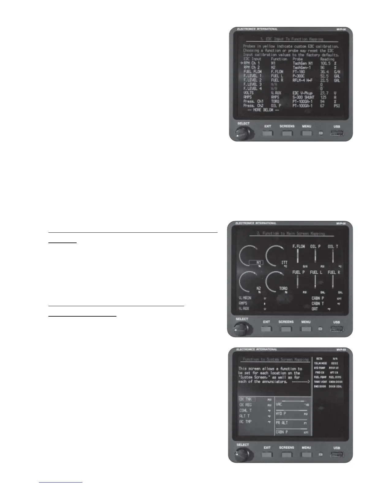
Note: Any one “Function” can only be assigned to a single
“EDC Input.” To change a Function on one EDC Input to
another EDC Input, first set the Function to “N/A” and then
reassign the Function to the new EDC Input. Functions
appear in alphabetical order. “N/A” appears before “A” and
after “Z.”
The “Reading” column at the far right of the screen shows the
current reading for each EDC Input. This can be used to
troubleshooting a channel (e.g., you can heat a temperature
probe or apply pressure to a pressure transducer and see
which EDC Input responds).
If a probe listed in the “Probe” column is shown in yellow, the
calibration of the EDC Input for that probe has been changed
from factory default. EDC Input calibration can only be changed in screen #5. Changing the calibration for an
EDC Input is for advanced users and normally is not recommended.
The EDC fuel level, pressure and temperature inputs can be configured for many different functions using
standard and/or custom probes. To calibrate an EDC Input to a custom probe, see the “5. EDC Input
Calibration Screen” section in this manual.
6.3.2 “2. Function to Main Screen Mapping”
Screen:
This screen allows you to customize the Main Engine Screen
by mapping functions into any of the four arc gauges, six
vertical gauges or six digital gauges.
6.3.3 “3. Function to System Screen
Mapping” Screen:
This screen allows you to customize the System Screen by
mapping a Function (that has been defined in the “1. EDC
Input to Function Mapping” screen) into any one of the seven
Digital gauges on the left side of this screen or any one of the
four Horizontal Strip gauges located on the right side of this
screen.
Also, annunciators may be mapped into the right portion of
this screen. The annunciators mapped into the left column
(top to bottom) of this screen will show in the top row (left to
right) on the Main Engine Screen. The annunciators mapped
into the right column (top to bottom) of this screen will show
in the second row (left to right) on the Main Engine Screen.
34

 Loading...

