35
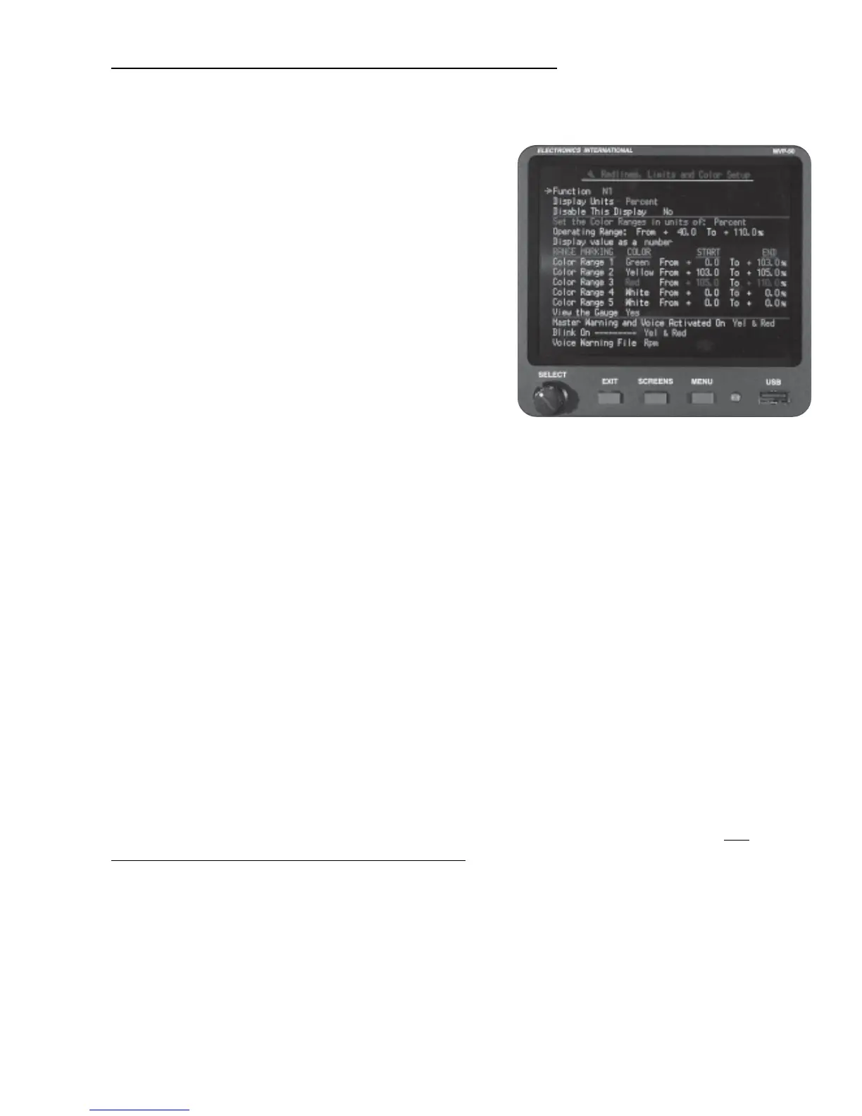
6.3.4 “4. Redlines, Limits and Color Setup” Screen:
This screen allows you to program up to five Color Ranges for any Function.
“Function:” This field allows you to select which Function
will be programmed.
“Disable This Display:” A “Yes” is this field will cause a
function to be displayed with the words “Disabled” in the
digital section of the gauge. If a function is inaccurate or
operating improperly, it should be disabled.
“Display Units:” For most Functions you may select the
units in which the Function will be displayed on the Main
Engine Instrument Screen.
“Set the Color Ranges in units of:” The Color Ranges
for a Function must be set in the units listed in this field. The
“Display Units” field above sets the units in which the
Function will be displayed on the Main Engine Screen.
“Displayed Operating Range (From__To__):” These fields allow you to set the operating range of the
Arc or Horizontal Strip Gauges. Note: Set the “To” field approximately 5% over the maximum operating
limit. This allows room for the red limit area to show up on the arc or horizontal strip.
“Color Range 1 to 5:” Each color used to set the various ranges of operation have a priority. The priority,
starting from the lowest to highest, is White, Green, Blue, Orange, Pink, Yellow and Red. If one color’s
operating range overlaps another’s, the color with the higher priority will overwrite the color with the lower
priority. Normally the colors blue, orange and pink should only be used to set narrow markers in an Arc or
Horizontal Strip Gauge. A narrow marker can be used to designate RPM or MP values required to achieve
specific climb or descent rates, mark a fuel flow setting for leaning or mark a narrow reference spot on a
gauge.
Refer to your aircraft’s POH when setting the Color Ranges. Start with the lowest value and work up to the
highest. The color white is the default color. If an area is not designated by any color, it will be displayed as
white.
FAR 21.1549 requires that the maximum and minimum safe operating ranges be marked in Red, any
precautionary ranges be marked in Yellow and the normal operating range be marked in Green.
It is
important to adhere to FAR 23.1549 requirements.
“Master Warning and Voice Activated On:” The external Master Warning Light and the Voice Warning
System may be disabled, set to alarm when a Red operating range is reached or set to alarm when a Red or
Yellow operating range is reached.
“Blink On”: The blinking of a digital display may be disabled, set to blink when a Red operating range is
reached or set to blink when a Red or Yellow operating range is reached. Note: If the “Master Warning and

 Loading...

