Voice Activated On” field is set to “Yel & Red,” The “Blink On” field will automatically be set to “Yel & Red.”
Any time the Master External Warning Light turns on, the digital display (for the function that activated the
Master External Warning Light) must blink.
“Voice Warning File”: This line sets the voice file that will be played when a red and/or yellow warning is
reached (as determined by the “Master Warning and Voice Activated On” field).
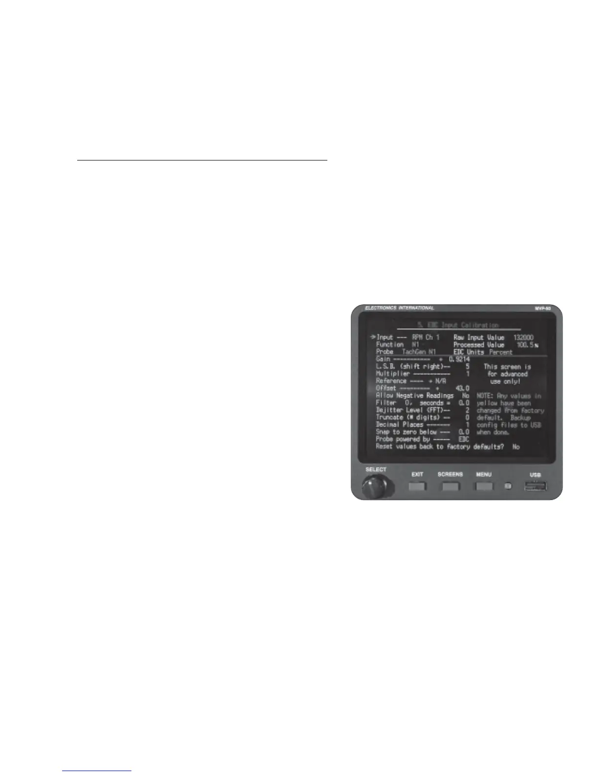
6.3.5 “5. EDC Input Calibration” Screen:
Warning: This screen is for advanced use only and data in this screen should normally not be changed.
This screen allows you to change the calibration parameters of an EDC Input used for a specific Probe and
Function. In this screen an EDC Input can be set up to accommodate a wide variety of nonstandard probes.
If any parameter for an EDC Input has been changed from the factory default, the changed parameters will be
displayed in yellow.
This screen provides the follows:
“Input:” Select the EDC Input to be modified in this field.
“Function:” This field displays the Function assigned to
the EDC Input selected above.
“Probe:” This field displays the Probe assigned to the
EDC Input selected above.
“Raw Input Value:” This field displays the value of the
uncalibrated signal measured on the EDC Input selected
above.
“Processed Value:” This field displays the value of the
calibrated signal measured on the EDC Input selected
above. The Raw Input Value is calibrated by the
calibration parameters listed below.
“EDC Units:” This field displays the processed units, which may not be the same as the displayed units.
The MVP performs a conversion to change the processed units to displayed units. You can select the
displayed units in Screen # 3.
Calibration Parameters: The Raw Input Value read from the EDC is processed (in sequence) by the
following calibration parameters:
“Gain:” The Raw Input Value from the EDC is multiplied by the number in this field. An Interim
Value is produced. Values over one should not be used.
“L.S.B. (shift right):” This field determines how many binary logic shift right processes are
performed on the Interim Value. Each shift operation divides the Interim Value by 2.
36

 Loading...

