9
2.5 Annunciators:
An EDC temperature or resistive fuel level channel can be connected to a switch, relay or device via a VI-221
interface circuit. The signals from these devices are usually high or low and can be used to generate an annunciator.
An annunciator can be displayed in any color for a high or low signal. If the color white was selected for one of the
signal levels, the annunciator will not be displayed for that signal level.
TANK VENT
FUEL
BAG DOOR
DOOR SEAL
FUEL BYPS
AFT CHPITOT HT
DEICE
ISLM MSG
BETA
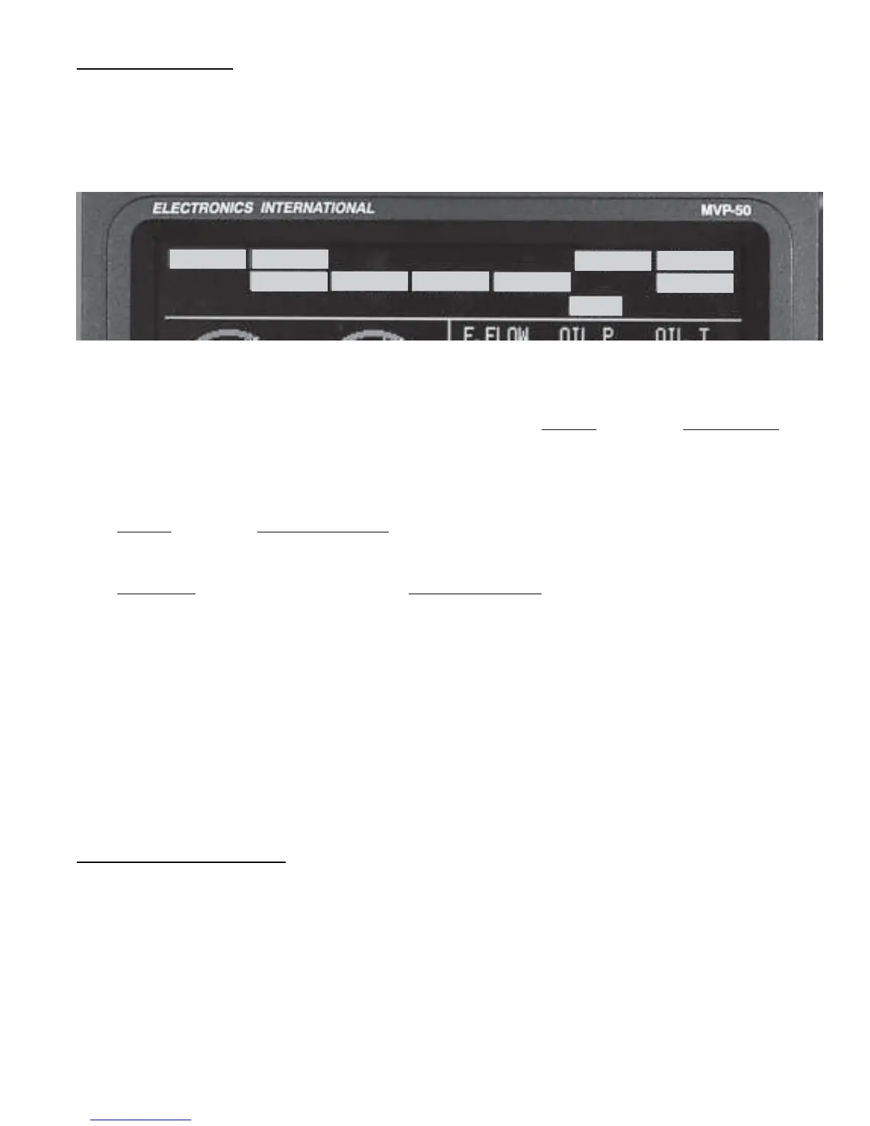
At the top of the Main Engine Screen are three rows of annunciators. The top two rows of annunciators are defined
by the installer. The bottom row of annunciators is associated with functions displayed on the Main Engine Screen.
Also, at the far right of the bottom row is a “System” annunciator. If any function found on the System Screen goes
into the red or yellow, the “System” annunciator will blink the appropriate color. In this way the pilot is alerted of a
potential problem and should view the System Screen for further information and to stop the “System” annunciator
from blinking.
If any function found on the Main Engine Screen goes into the red or yellow, the appropriate annunciator in the
bottom row will blink.
If any annunciator found on the top two rows of the Main Engine Screen goes to any color other than white, the
appropriate annunciator will light. If the lit color is red or yellow, the appropriate annunciator will also blink.
To stop the blinking of any annunciator, push any button, or rotate the SELECT knob while viewing the Main Engine
Screen. Also, acknowledging a voice warning using the external “Voice Alarm Control Panel” will stop the blinking
regardless of what screen you are viewing.
Note: Blinking on red and/or yellow for any functions can be disabled in the “4. Redlines, Limits and Color Setup”
screen (see section 6.3.4).
Note: To test the annunciators, push and hold the “Exit” button. All available annunciators will light.
2.6 Digital Instruments:
At the bottom of the Main Engine Screen are three areas for digital instruments. The bottom center section may be
switched between Trim (includes Gear and Flaps), Clocks, Flight Timer, Down Timer and Up Timer. Push and turn
the “Select” knob to display the various functions.
If a function displayed on a digital instrument goes in the red or yellow operating range, the digital display will blink
the appropriate color. To stop the blinking, push any button, or rotate the SELECT knob while viewing the Main
Engine Screen. Also, acknowledging a voice warning using the external “Voice Alarm Control Panel” will stop the
blinking regardless of what screen you are viewing.

 Loading...

