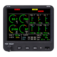
6.2.6 “MVP Input/Output Tests” Screen:
This screen allows you to test the various MVP input and output lines. This screen can be very useful in
troubleshooting system problems.
6.3 “EDC Inputs, Functions and Screen Setup” Section:
Probes and transducers are mechanically connected to the aircraft and are electrically connected to the EDC
(Engine Data Converter). The EDC converts the analog signals from the probes to digital signals and then transmits
them to the MVP. The following screen allow you to display a function on an MVP screen and set the redlines and
limits. The five screens in this section perform the following:
Screen #1: This screen assignes a Function and Probe to an EDC input. The Probe sets the calibration
parameters found in screen #5.
Screen #2: This screen allows you to select a Main Engine Screen location on which the Function will be
displayed.
Screen #3: This screen allows you to select a System Screen location on which the Function will be
displayed.
Screen #4: This screen allows you to set the display units, operating range, limits and color ranges for each
Function.
Screen #5: This screen is for advanced use only and allows you to change the probe calibration data for any
Function.
6.3.1 “1. EDC Input to Function Mapping” Screen:
The installer should record which probes and transducers are connected to the various EDC (Engine Data
Converter) inputs on the EDC Wiring Work Sheets (found in the MVP-50P Installation Instructions). The
“EDC Input” column shown in this screen is a list of all the input channels available on the EDC. Also, input
channels for a second EDC are provided at the bottom of this list.
This screen allows you to select a Function for each EDC Input. After the Function is selected you may select
the Probe. The Probe on the screen should match the one installed in the aircraft for this Function (refer to
your EDC Wiring Work Sheets).
Example: EDC Input Function Probe
Press. Ch2 Oil P. PT-100GA-1
33

 Loading...